
Apparatus for arrange spacer of a field-emission display

Inactive Publication Date: 2006-01-12
TECO NANOTECH CO LTD
View PDF1 Cites 4 Cited by
  • Summary
  • Abstract
  • Description
  • Claims
  • Application Information

AI Technical Summary

Benefits of technology

[0006] An apparatus for installing a spacer of a field-emission display is also provided having a support member, a suction mechanism and a vacuum breaking device. One end of the suction mechanism is connected to the support member, and the other end of the suction mechanism has an opening for sucking the top portion of the spacer and a positioning part for aligning the spacer. The vacuum breaking device to provide an electrostatic removal gas to prevent electrostatic charges generated between the spacer and the suction mechanism.

Problems solved by technology

Those spacers selected from sodalime or similar material all experience of brittle, difficult to retrieve and align, and the complex fabrication.
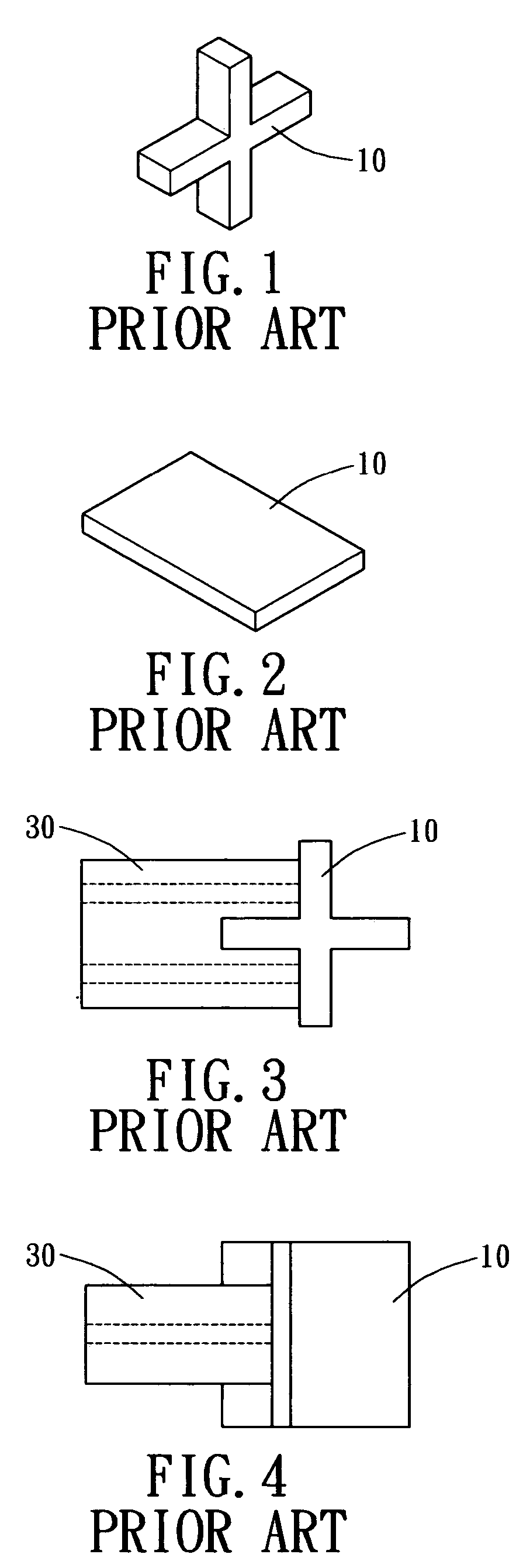
The drawback is than the side-suction results in a transverse reaction to display the spacer 10 when the spacer is removed from the suction mechanism.
Further, as the material of the spacer easily generate electrostatic charges, particularly during removal of the spacer 10 from the suction mechanism, the spacer is difficult to be removed.

Method used


Image

  • Apparatus for arrange spacer of a field-emission display
  • Apparatus for arrange spacer of a field-emission display
  • Apparatus for arrange spacer of a field-emission display

Examples


Embodiment Construction

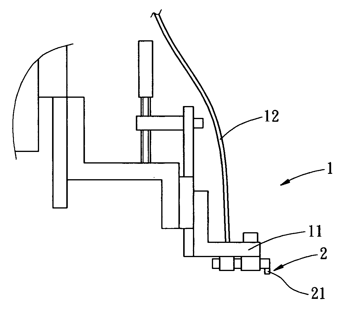
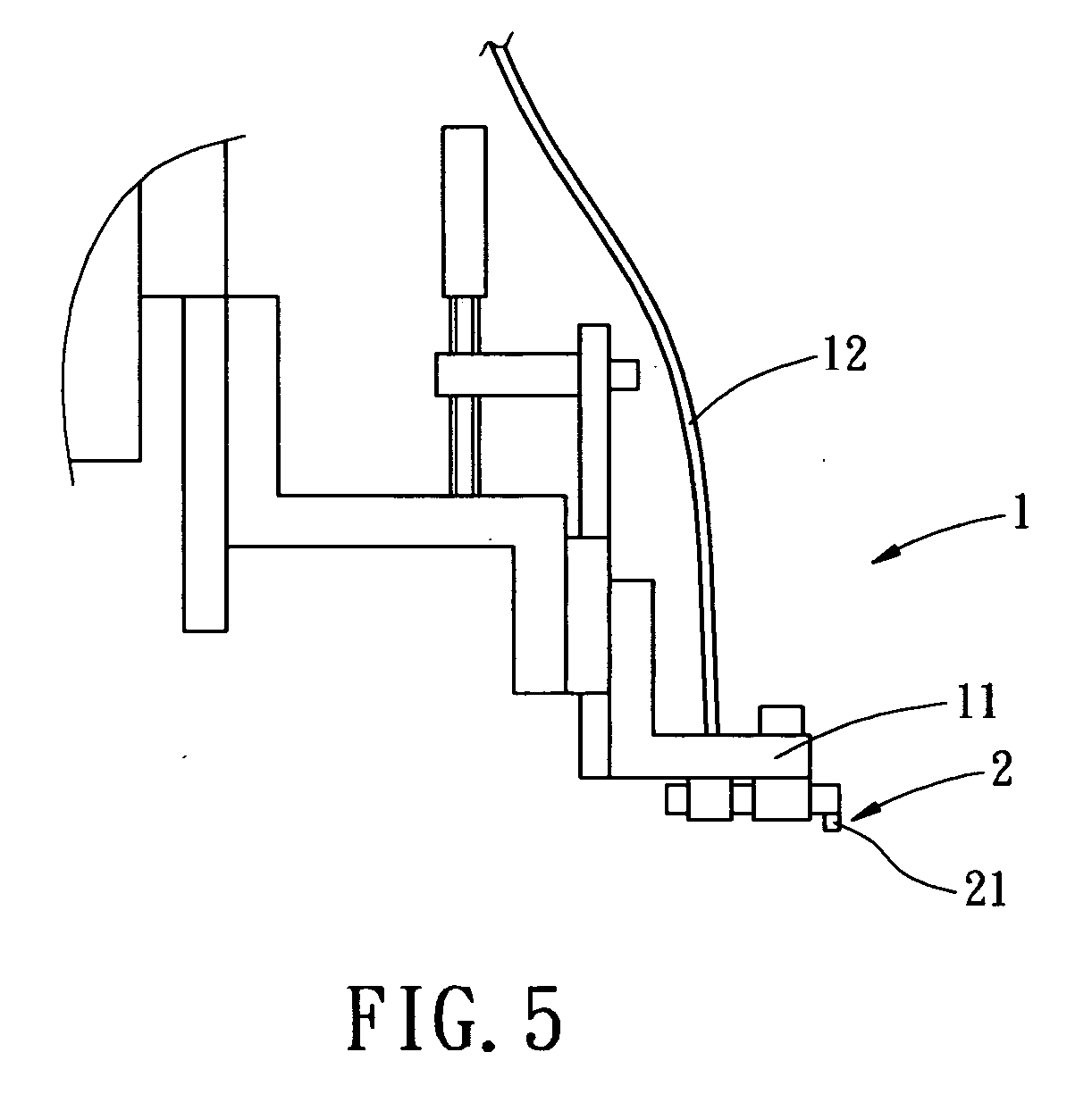
[0019]FIGS. 5 and 6 shows the rear view of an apparatus for installing a spacer and a suction structure. As shown, the apparatus for installing the spacer of a field-emission display uses suction force generated by the suction structure to suck the spacer 10 as shown in FIGS. 1 and 2. The spacer 10 is then installed between the anode board (not shown) and the cathode board (not shown) of the field-emission display. Thereby, the luminescent efficiency of the phosphor on the anode is enhanced, and the breakdown voltage between the anode board and the cathode board will not be too low to affect the image.

[0020] The suction structure includes support element 11 mounted to an installation device 1, a gas transmission device 12 connected to the suction structure 10 for venting the gas sucked by the suction structure 10, a suction mechanism, which includes a suction terminal and a suction opening 22 facing downwardly. A positioning part 23 for positioning or holding the spacer 10 sucked b...


PUM

PropertyMeasurementUnit
Forceaaaaaaaaaa
Diameteraaaaaaaaaa
Configurationaaaaaaaaaa

Abstract

An apparatus for installing a spacer of a field-emission display is provided with a suction mechanism for sucking the spacer. The suction mechanism has a suction terminal, which an opening to apply suction force on top of the spacer and a positioning part located on top of the suction terminal for positioning the spacer sucked by the suction terminal. The suction terminal includes a pipe having a diameter smaller than that of the spacer. The positioning part is configured according to a configuration of the spacer. The opening has a uniform cross section from a bottom edge to a top surface thereof or a cross section gradually decreasing from a bottom edge to a top surface thereof.

Description

BACKGROUND OF THE INVENTION [0001] The present invention relates in general to an apparatus for installing a spacer of a field-emission display, and more particularly, to an apparatus operative to provide suction force normal to the spacer, such that the spacer can be disposed between the anode and cathode boards and aligned therewith. Further, the apparatus uses a vacuum breaking device to prevent electrostatic charges from be generated, particularly during the removal of the spacer from the apparatus. [0002] Currently, the bipolar, tripolar or tetrapolar field emission displays all contain a spacer 10 between the cathode and anode boards (as shown in FIGS. 1 and 2). The spacer 10 is designed to enhance the luminescent efficiency without overly reducing the breakdown voltage between the cathode and anode boards. Therefore, the space between the cathode and anode boards is typically maintained no smaller than 500 microns by the space 10. Therefore, the spacer 10 has to be strong eno...

Claims


Application Information

Patent Timeline
IPC IPC(8): B23P19/00
CPCH01J9/185H01J9/242H01J31/123Y10T29/49133Y10T29/5313Y10T29/53191H01J2329/8625
Inventor YANG, FRANK
Owner TECO NANOTECH CO LTD
Learn More