
Image forming and reproducing apparatus, and image transferring method

a technology of image forming and reproducing apparatus, applied in the direction of electrographic process apparatus, instruments, optics, etc., can solve the problems of color image misalignment, and delaying the actual image forming and reproducing operation, so as to reduce the time required for correction and improve the correction accuracy. the effect of image misalignmen

Inactive Publication Date: 2006-01-05
RICOH KK
View PDF6 Cites 24 Cited by
  • Summary
  • Abstract
  • Description
  • Claims
  • Application Information

AI Technical Summary

Benefits of technology

[0011] The present invention was conceived in view of the above-described problems, and it is an object of the invention to provide an image forming and reproducing apparatus and an image transferring method that can improve the correction accuracy for image misalignment, while reducing time required for the correction for image misalignment.
[0017] Accordingly, even if misalignment occurs in the superposed images due to error in distance between image carriers or error in component precision or assembling accuracy of the image writing system, the image misalignment can be appropriately corrected under control of the rotation speeds of the image carriers so as to bring time required for the images on the image carriers to reach the transferred positions in agreement with each other.
[0018] Image misalignment caused by error in distance between image carriers or error in component precision or assembling accuracy of the image writing system is unlikely to greatly vary until the image carriers or the image writing system is detached for maintenance or other reasons. Accordingly, the rotation speeds of the image carriers are set when, for example, the apparatus is powered on, and consequently, image misalignment correcting time can be reduced.
[0019] The image misalignment correction technique of the present invention is distinguished from the conventional dot-by-dot based correction for image misalignment performed when images are formed on image carriers (photosensitive drums). With the present invention, image misalignment is corrected by bringing time required for the images formed at the exposure positions of the image carriers to reach the transfer positions in agreement with each other among the image carriers. Consequently, subtle deviation of each color image within a dot can be corrected according to the resolution of the rotation speed of the image carrier.
[0020] The precision of misalignment correction can be improved, while time required for the correction for image misalignment can be reduced.

Problems solved by technology

However, since the phase difference has to be corrected every time a rotational phase difference is produced, the operationability and the functionality are degraded.
This means that the actual image forming and reproducing operation is delayed every time misalignment correction is carried out.
In general, misalignment of color images formed by different photosensitive drums and superposed on each other to form a combined image is often caused by error in distance between photosensitive drums, as well as in machining and assembling accuracy of components used in the image writing unit.
Since the image misalignment is corrected on the dot basis, subtle offset of images within a dot cannot be corrected although such minute offset is likely to affect evenness of color and delicate hue.

Method used


Image

  • Image forming and reproducing apparatus, and image transferring method
  • Image forming and reproducing apparatus, and image transferring method
  • Image forming and reproducing apparatus, and image transferring method

Examples


Embodiment Construction

[0033] The preferred embodiments of the present invention are now described below, in conjunction with the attached drawings.

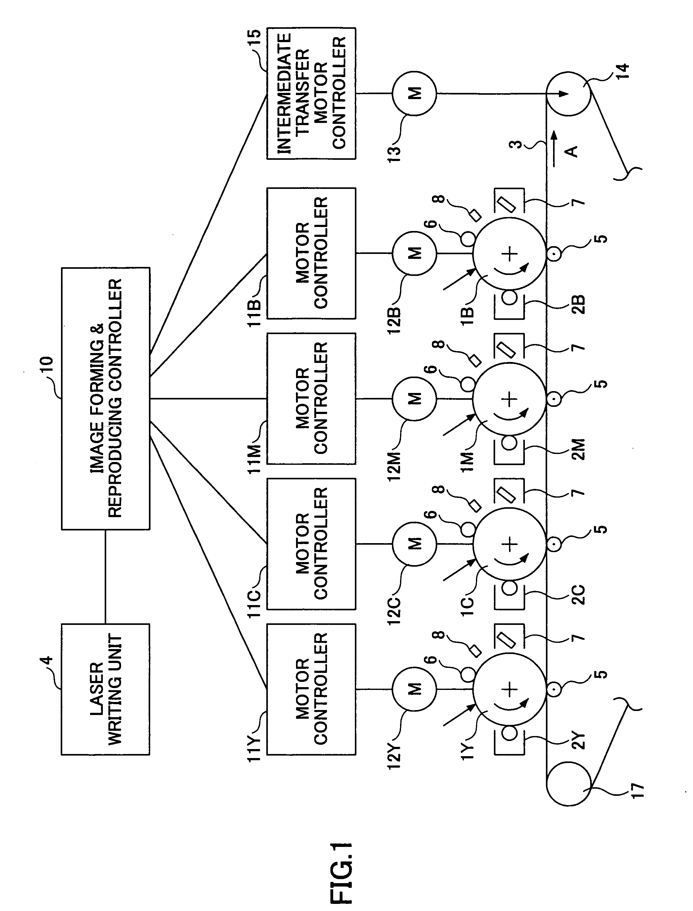
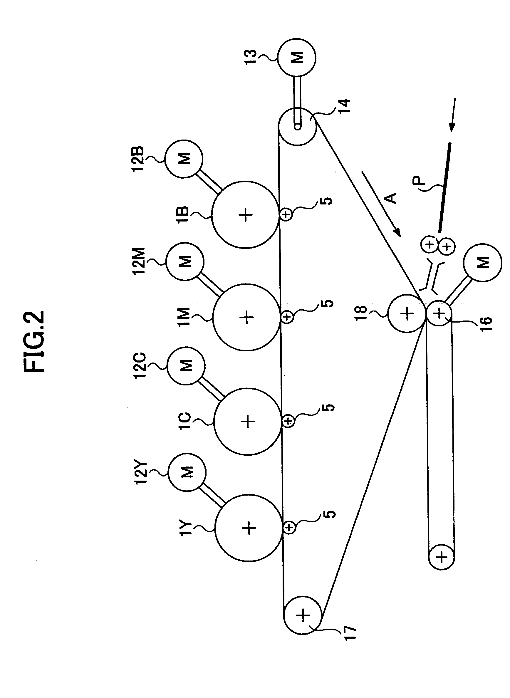
[0034]FIG. 1 illustrates a control system and FIG. 2 illustrates an image forming and reproducing system of an image forming and reproducing apparatus according to an embodiment of the invention. FIG. 3 is a block diagram used to explain the motor control for the image forming and reproducing apparatus.

[0035] The image forming and reproducing apparatus has multiple photosensitive bodies 1Y, 1C, 1M and 1B (referred to simply as “photosensitive bodies 1” when not specified), and associated development units 2Y, 2C, 2M and 2B (referred to simply as “development units 2” when not specified). This apparatus shown in FIG. 1 is a tandem type electrophotographic printing apparatus (a color copier or a color printer), in which a single-color toner image is formed on each of the photosensitive bodies 1. The toner images on the photosensitive bodies 1 are successively ...


PUM


Abstract

An image forming and reproducing apparatus is configured to transfer images formed on multiple rotatable image carriers (1Y, 1C, 1M, and 1B) onto a transfer member (3) at associated transfer positions (P1-P4). The apparatus includes a rotation speed controller that controls the rotation speeds of the image carriers such that times required for the images formed at exposure positions of the image carriers to reach the associated transfer positions agree with each other among the image carriers when superposing the images one on the other on the transfer member.

Description

BACKGROUND OF THE INVENTION [0001] 1. Field of the Invention [0002] The present invention relates to an image forming and reproducing apparatus and an image transferring method, and more particularly, to an image forming and reproducing apparatus with independently rotated image carriers on which images of different colors are to be formed, as well as to an image transferring technique used in such an image forming and reproducing apparatus. [0003] 2. Description of Related Art [0004] Conventionally, color image forming and reproducing apparatuses are known. In such an apparatus, different color images (such as black, yellow, magenta, and cyan images) are formed separately on associated photosensitive drums or image carriers which serve as image carriers and are rotated independently by driving motors and serving as image carriers. The color images formed on the photosensitive drums are transferred onto an intermediate transfer belt. [0005] Conventionally, such an image forming and ...

Claims


Application Information

Patent Timeline
Patent Type & Authority Applications(United States)
IPC IPC(8): G03G15/01G03G21/14
CPCG03G15/5008G03G2215/0141G03G2215/0129G03G2215/0119
Inventor IWASAKI, HIROYUKI
Owner RICOH KK
Learn More