
Using physical objects to adjust attributes of an interactive display application

a technology of interactive display and physical objects, applied in computing, instruments, electric digital data processing, etc., can solve the problem that systems are generally limited to responding to a specific obj

Inactive Publication Date: 2006-01-05
MICROSOFT TECH LICENSING LLC
View PDF13 Cites 628 Cited by
  • Summary
  • Abstract
  • Description
  • Claims
  • Application Information

AI Technical Summary

Benefits of technology

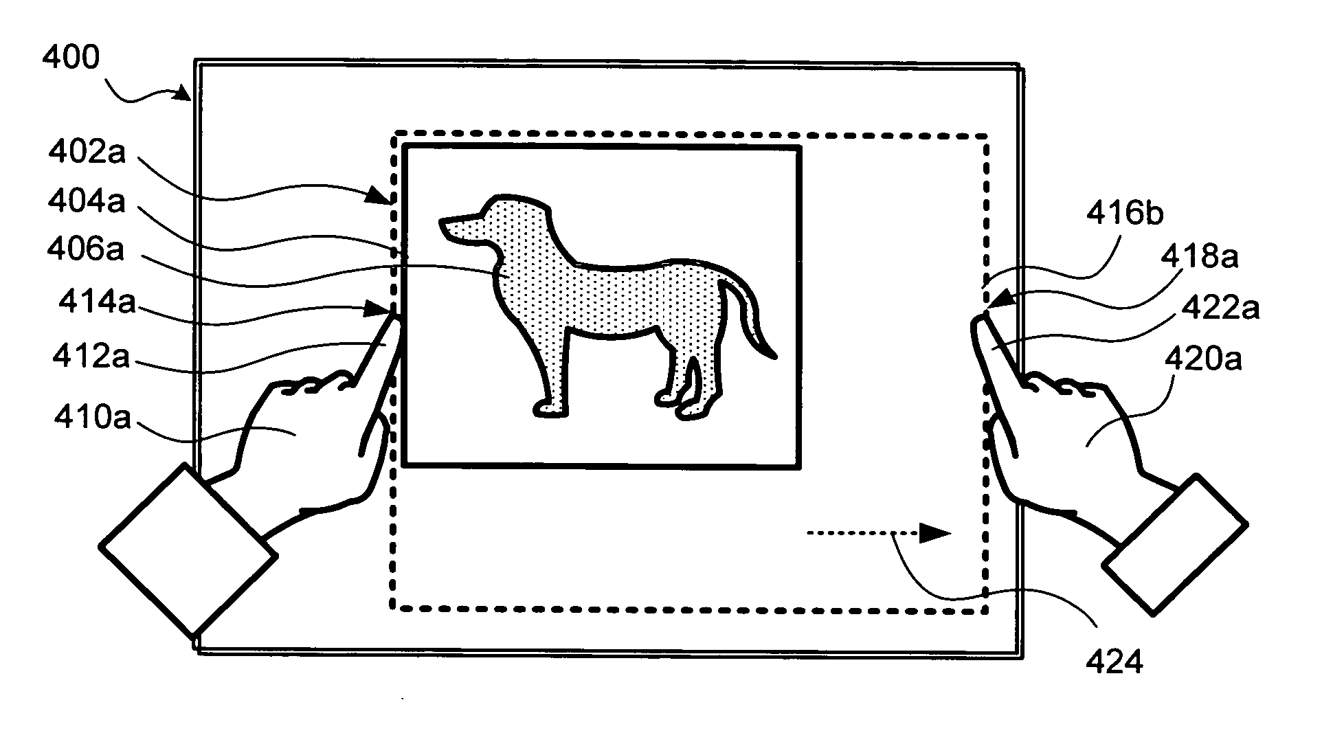
[0008] One of the advantages of the present invention is that it provides a convenient, natural, and intuitive manner for a user to interact with a computer system having an interactive display surface. In conventional systems, a user responds to images or other attributes of applications presented on a display by engaging a keyboard, a pointing device, or another input device that is separate and removed from the display. In contrast, the present invention enables a user to employ physical objects, such as fingers and thumbs of the user's hand, to modify images presented on the interactive display surface. Similarly, a user can use digits on the user's hands or other physical objects to modify attributes of an application executing on the computer system associated with the interactive display surface. Thus, a user can provide input to the computer system by interacting directly with the output of the computer system to provide the input. While the present invention is particularly useful in resizing or cropping images that are rectangular, it should be understood that the user's fingers or hands or other physical objects can be applied in resizing or cropping virtual entities other than rectangular images. For example, the user can interact with irregularly-shaped virtually entities or with three-dimensional entities to resize or crop them, just as discussed below in regard to resizing or cropping images.

Problems solved by technology

Such systems are generally limited to responding to a specific object in a predefined manner.

Method used


Image

  • Using physical objects to adjust attributes of an interactive display application
  • Using physical objects to adjust attributes of an interactive display application
  • Using physical objects to adjust attributes of an interactive display application

Examples


Embodiment Construction

Exemplary Computing System for Implementing Present Invention

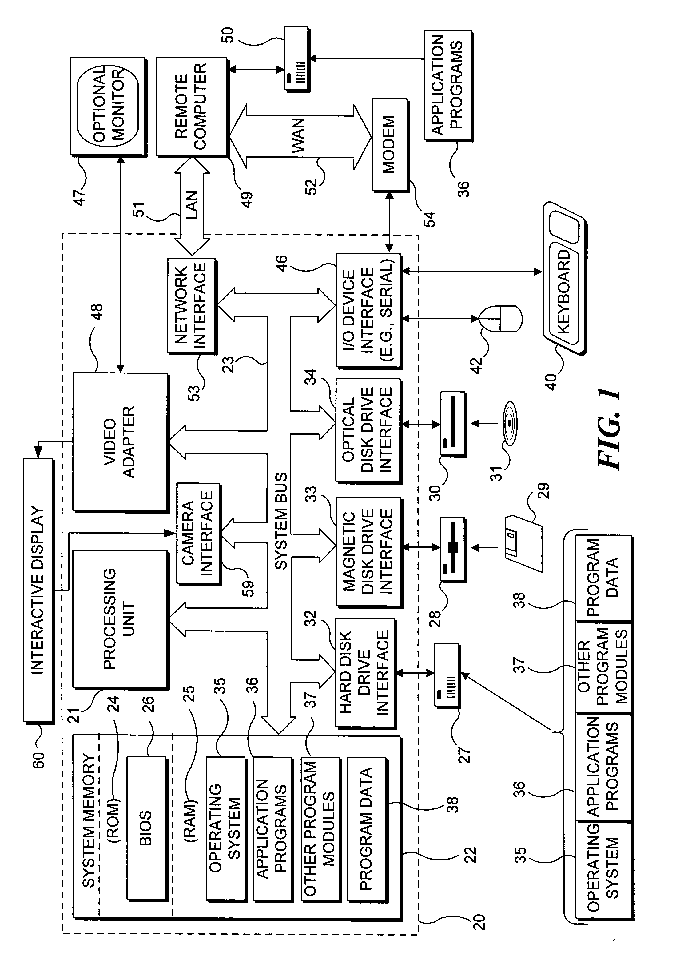
[0032] With reference to FIG. 1, an exemplary system suitable for implementing various portions of the present invention is shown. The system includes a general purpose computing device in the form of a conventional PC 20, provided with a processing unit 21, a system memory 22, and a system bus 23. The system bus couples various system components including the system memory to processing unit 21 and may be any of several types of bus structures, including a memory bus or memory controller, a peripheral bus, and a local bus using any of a variety of bus architectures. The system memory includes read only memory (ROM) 24 and random access memory (RAM) 25. A basic input / output system 26 (BIOS), containing the basic routines that help to transfer information between elements within the PC 20, such as during start up, is stored in ROM 24. PC 20 further includes a hard disk drive 27 for reading from and writing to a hard disk ...


PUM


Abstract

Input is provided to an application using a plurality of physical objects disposed adjacent to an interactive display surface. A primary location is determined where a primary physical object, e.g., a finger or thumb of the user, is positioned adjacent to the interactive display surface. An additional location is determined where an additional physical object is positioned adjacent to the interactive display surface. The attribute might be a size of an image or selected portion of the image that will be retained after cropping. A change in position of at least one of the objects is detected, and the attribute is adjusted based on the change in position of one or both objects. A range of selectable options of the application can also be display by touching the interactive display surface with one's fingers or other objects, and one of the options can be selected with another object.

Description

FIELD OF THE INVENTION [0001] The present invention generally pertains to a computing system having an interactive display surface operable to detect physical objects placed adjacent to the interactive display surface, and more specifically, to detect positions and movements of the physical objects to provide input to change one or more attributes of an application being executed by the computing system. BACKGROUND OF THE INVENTION [0002] Personal computers (PCs) have become increasingly more powerful in many different respects. One example of the increased power of computers is in their tremendously improved graphics capabilities. While early PCs were limited to four colors and pixilated low resolution displays, contemporary computers provide colorful, high-resolution graphics that are more than suitable for viewing digital photographs or watching movies as well as enabling display of fast moving virtual images in games and other applications. [0003] The improved power of computers...

Claims


Application Information

Patent Timeline
Patent Type & Authority Applications(United States)
IPC IPC(8): G09G5/00
CPCG06F3/0421G06F3/0482G06F2203/04806G06F3/0488G06F3/04845
Inventor ROBBINS, DANIEL C.DRUCKER, STEVEN M.WILSON, ANDREW D.NYE, KRISTEN NILSENDEHLIN, JOEL P.
Owner MICROSOFT TECH LICENSING LLC
Learn More