
Capsule endoscope

a capsule and endoscope technology, applied in the field of endoscopes, can solve the problems of difficult swallowing of capsules, excessive outer diameter of capsules, and obstruction of the central region's view field, and achieve the effect of improving the ease of swallowing and ensuring the observation field

Inactive Publication Date: 2005-12-29
OLYMPUS CORP
View PDF6 Cites 28 Cited by
  • Summary
  • Abstract
  • Description
  • Claims
  • Application Information

AI Technical Summary

Benefits of technology

The present invention is about a capsule endoscope that can be swallowed to examine the interior of a living body. The invention aims to make the capsule smaller and easier to swallow while maintaining a sufficient field of view for observation. It also aims to provide good images over the entire field of view without increasing the total length of the capsule. Additionally, the invention makes the near point distance larger in a central region of the field of view than in a region of the field of view that is peripheral to the cental region. This enables deeper regions to be imaged in focus in the central region of the field of view. The invention does not degrade the imaging performance of the capsule endoscope by making the near point of focus deeper in the central region.

Problems solved by technology

In these conventional examples, because an objective lens and an illumination body are fixed inside a near-hemispherical transparent cover and the curvature radius is the same between the central region of the field of view and the peripheral region of the field of view, there was an inconvenience in that the mucosa layer easily contacts the central region of the transparent cover, causing an obstruction in the field of view of the central region.
Also, when the transparent front cover has a single radius of curvature (i.e., one defined by one-half the outer diameter of the capsule that is fitted to the transparent cover), the outer diameter of the capsule becomes excessive, making the capsule difficult to swallow and giving it low motility when within the body.

Method used


Image

  • Capsule endoscope
  • Capsule endoscope
  • Capsule endoscope

Examples


embodiment 1

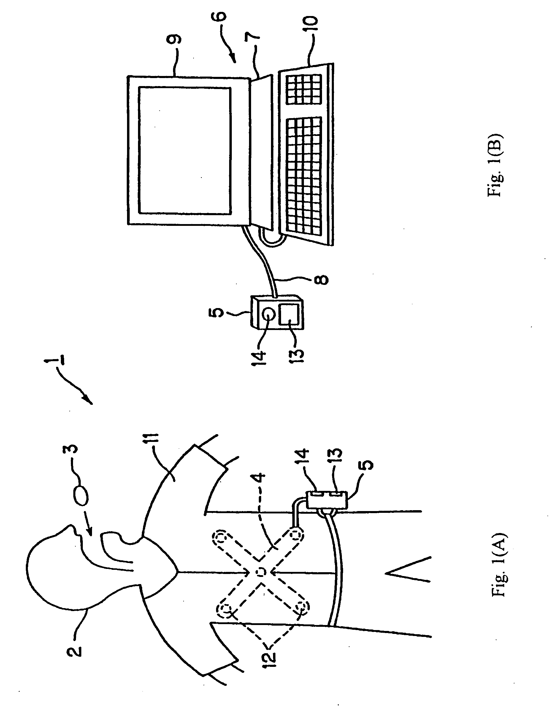
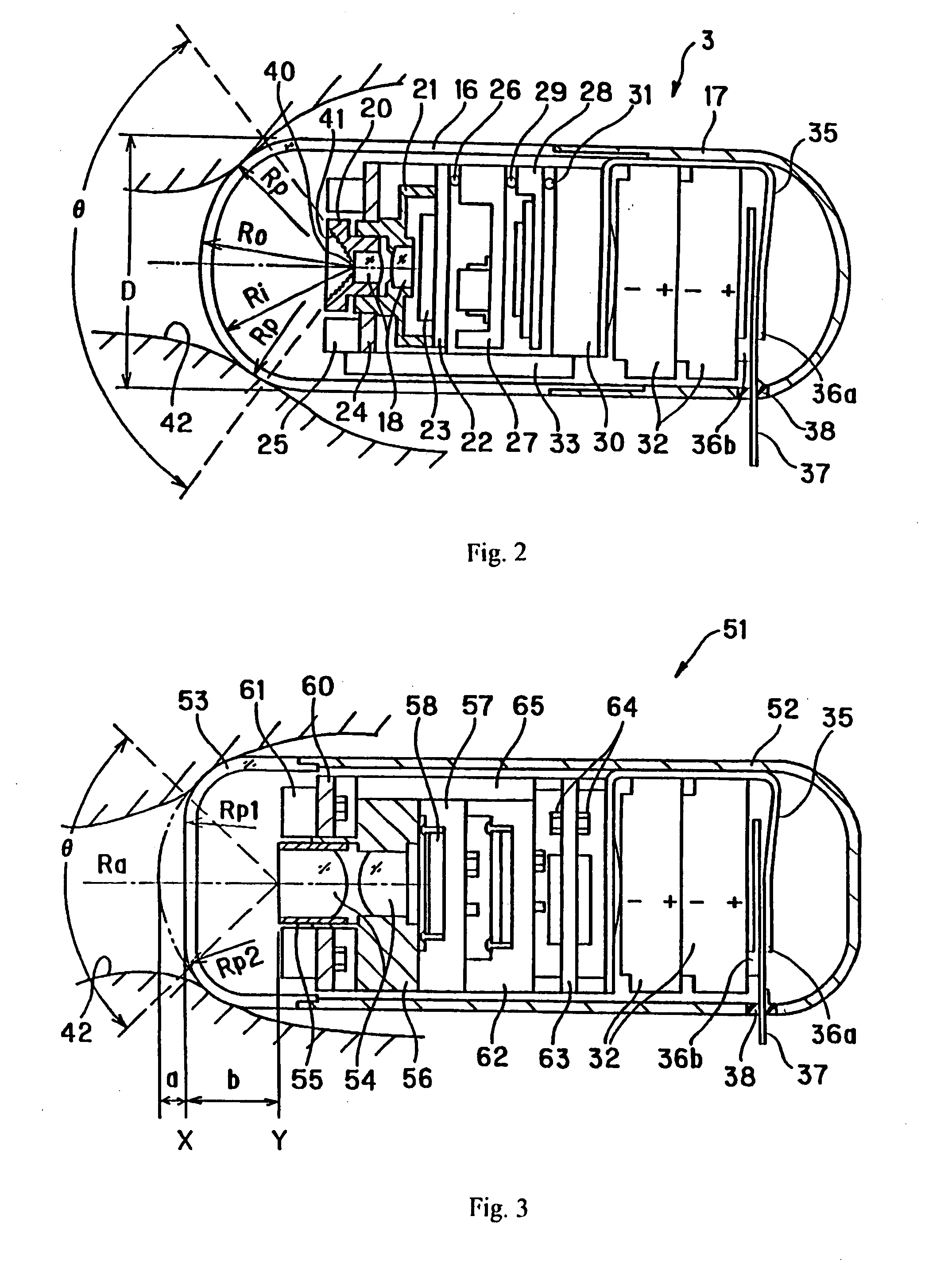
[0016] Embodiment 1 will be described with reference to FIGS. 1(A), 1(B) and 2. FIGS. 1(A) and 1(B) show the capsule endoscope system, with FIG. 2 being a cross-sectional view showing the internal configuration of the capsule endoscope according to this embodiment. As shown in FIG. 1(A), a capsule endoscope apparatus 1 which is equipped with the first embodiment for performing endoscopic examinations uses a capsule endoscope 3 which wirelessly transmits image signals of the internal walls of the tubes in a coelom while passing through such a tube after being swallowed by a patient 2. An external unit 5 (one that is placed outside the patient's body) receives radio signals transmitted by this capsule endoscope 3 through an antenna unit 4 and stores the images.

[0017] In this external unit 5, a memory unit such as a compact flash memory of 1 gigabyte capacity, for example, is used to store the image data. The external unit 5 can then be connected to a display system 6 (FIG. 1(B)) in o...

embodiment 2

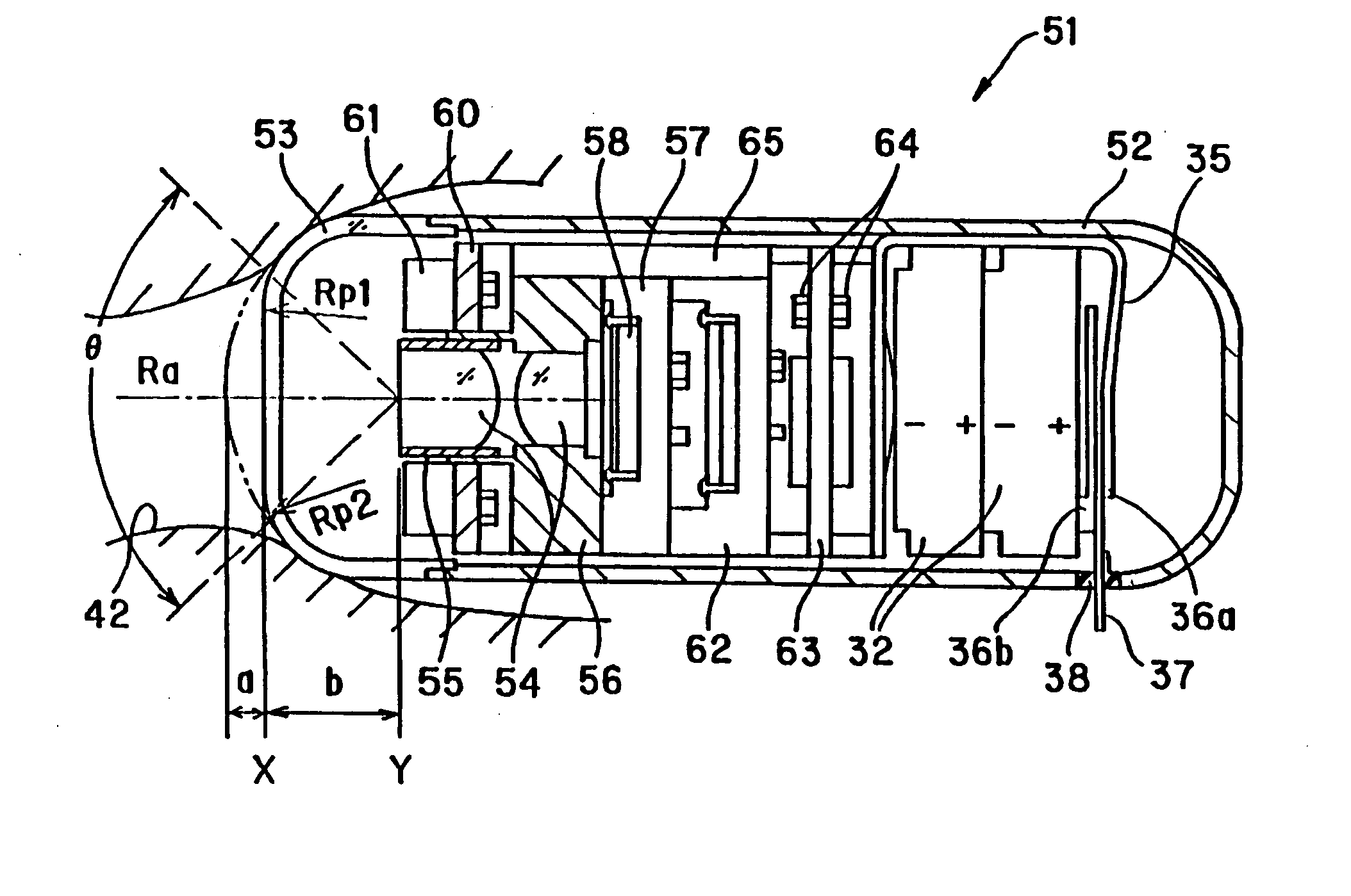
[0026]FIG. 3 is a cross-sectional view showing the internal configuration of a capsule endoscope 51 according to Embodiment 2 of the invention. In the capsule endoscope 51, a transparent front cover 53 is fitted and glued to the front end of a member 52 which has a cylindrical shape. The rear end of the capsule endoscope 51 is closed using a rounded shape, making the interior of the capsule endoscope 51 watertight. An objective optical system 54 is provided within the capsule endoscope. Behind a central region of the transparent cover 53, the objective optical system 54 is formed by attaching a first lens to the first lens frame 55 and a second lens to a second lens frame 56, respectively. At the image plane, a CMOS image sensor 58 is installed on a planar surface that forms the lower surface of a two-level recessed portion at a front surface of a circuit board 57. Nearer the front of the capsule, a circuit board 60 is matched and glued to a cylindrical section of the second lens fr...

embodiment 3

[0029]FIG. 4 is a cross-sectional view showing the internal configuration of a capsule endoscope according to Embodiment 3 of the invention. In the capsule endoscope 71 shown in FIG. 4, a transparent cover 73 that includes a hemispheric-shaped front end is water-tightly fixed to the open end section of a rear case 72 which has a cylindrical shape. The rear case 72 has its other end closed by a rounded shape.

[0030] The following components are contained within the capsule endoscope 71. At an axial position facing the transparent cover 73, there is an objective optical system 76 which is attached to a lens frame 75. At the image surface of the objective optical system 76 is placed a CMOS image sensor 78 which is protected by a cover glass 77. This CMOS image sensor 78 is mounted to the front surface of a circuit board 79. Of course, instead of a CMOS image sensor 78, a CCD image sensor can instead be used.

[0031] The objective optical system 76 consists of two plano-convex lens eleme...


PUM


Abstract

A capsule endoscope is disclosed having an illumination means, an imaging system that includes an objective optical system, and a transparent cover. The invention is characterized by one of: (1) the transparent cover has a larger radius of curvature in a central region of the field of view of the objective optical system than the radius of curvature of the transparent cover in a peripheral region of the field of view of the objective optical system, or (2) the imaging system has a different near point of focus distance for a central region of the field of view than the near point of focus distance of a region that is peripheral to the central region of the field of view and the objective optical system includes a meniscus lens element of positive refractive power and a plano-convex lens element.

Description

CROSS-REFERENCE TO RELATED APPLICATION [0001] This is a divisional application of allowed U.S. application Ser. No. 10 / 347,325, filed Jan. 21, 2003.BACKGROUND OF THE INVENTION [0002] In recent years, endoscopes have come to be widely used in both the medical field and in industry. Recently, endoscopes have been developed which do not require an inserted part and which avoid the pain associated with inserting an insertion part. In these endoscopes that are used in the medical field, a patient swallows an endoscope which has been miniaturized and placed within a capsule. For example, see Japanese Laid Open Patent Application No. 2001-91860 and published PCT application WO 01 / 65995 A2. [0003] In the above-mentioned patent application, an objective lens and an illumination means formed of a luminescent diode are installed inside a near-hemispherical transparent cover. An object to be observed is illuminated by a luminescent diode and an objective lens forms an image of the object on an ...

Claims


Application Information

Patent Timeline
Patent Type & Authority Applications(United States)
IPC IPC(8): G02B23/24A61B1/00A61B1/04H04N5/225H04N7/18
CPCA61B1/041A61B1/04
Inventor YOKOI, TAKESHIHASEGAWA, AKIRAMATSUMOTO, SHINYASUZUKI, TAKAYUKISEGAWA, HIDETAKETAKIZAWA, HIRONOBU
Owner OLYMPUS CORP
Learn More