
Disk chucking mechanism having a fan-shaped driving pin

a technology of fan-shaped driving pins and disk chucking mechanisms, which is applied in the direction of magnetic recording, data recording, instruments, etc., can solve the problems of difficult to obtain a stable generation timing of index signals, and increasing the number of assembling processes, so as to avoid the probability of mischucking and improve the reliability of the

Inactive Publication Date: 2005-12-29
MITSUMI ELECTRIC CO LTD
View PDF13 Cites 2 Cited by
  • Summary
  • Abstract
  • Description
  • Claims
  • Application Information

AI Technical Summary

Benefits of technology

[0020] It is another object of the present invention to provide a disk chucking mechanism of the type described, which is capable of avoiding probability of mischucking as much as possible.
[0021] It is still another object of the present invention to provide a flexible disk drive, which is capable of improving reliability thereof.

Problems solved by technology

It is difficult to obtain a stable generation timing for the index signal.
Accordingly, the conventional flexible disk drive is disadvantageous in that it requires a lot of parts and the number of processes for assembling increases.
In other words, eccentricity may occur.
That is, mischucking may occur because the rotor of the spindle motor rotates in the opposite direction.
As a result, it makes reliability of the flexible disk drive lower.

Method used


Image

  • Disk chucking mechanism having a fan-shaped driving pin
  • Disk chucking mechanism having a fan-shaped driving pin
  • Disk chucking mechanism having a fan-shaped driving pin

Examples


Embodiment Construction

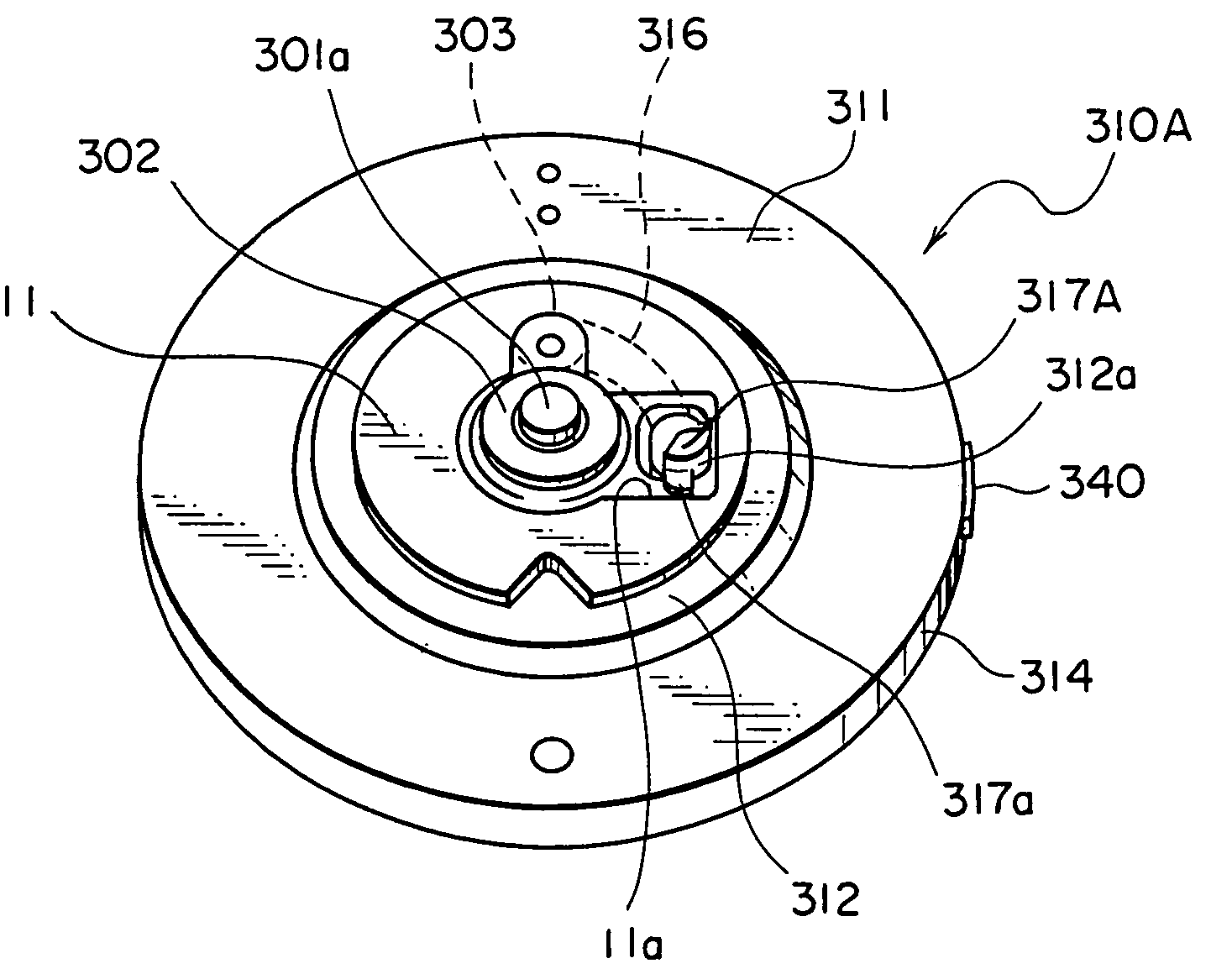
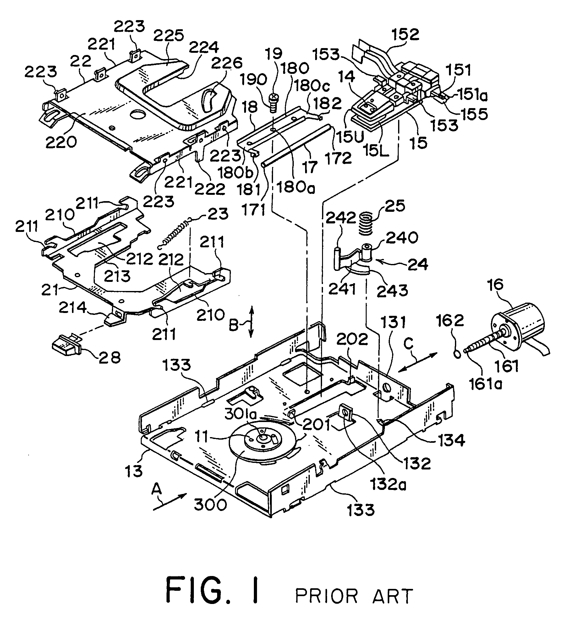
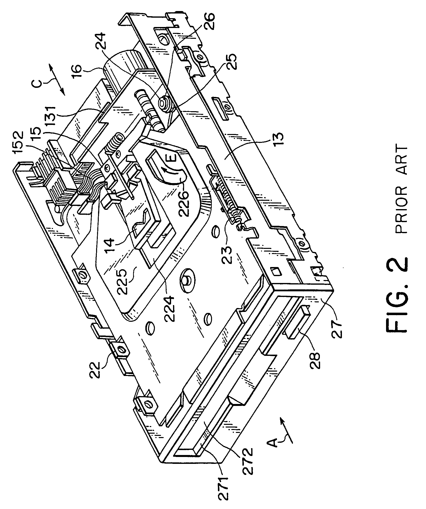
[0039] Referring to FIGS. 1 and 2, a conventional flexible disk drive of a 3.5-inch type will be described at first in order to facilitate an understanding of the present invention. The illustrated flexible disk drive has a frame structure proposed in the above-mentioned U.S. Pat. No. 6,747,831. FIG. 1 is an exploded perspective view of the conventional flexible disk drive. Although the conventional flexible disk drive has a front panel and a case, they are omitted in FIG. 1. FIG. 2 is a perspective view of the conventional flexible disk drive viewing from a front side. An upper cover (the case) is omitted in FIG. 2.

[0040] The illustrated flexible disk drive is a device for driving a flexible disk of a 3.5-inch type (which will later be described). The flexible disk is loaded or inserted in the flexible disk drive from a direction indicated by an arrow A in FIGS. 1 and 2. The loaded flexible disk is held on a disk table 11 having a spindle shaft which will later be described. In th...


PUM


Abstract

In a disk chucking mechanism for use in a flexible disk drive adopting a spindle motor (300) of a Hall sensor-less method, a driving pin (317A) freely received in a driving oval hole (46b) of a flexible disk (40) has a shape (shape of fan) where a catch factor portion is cut so that the driving pin (317A) is not in contact with an inner edge of the driving oval hole (46b) as much as possible when a rotor (310A) of the spindle motor (300) rotates in the opposite direction (counterclockwise).

Description

[0001] This application claims priority to prior Japanese patent application JP 2004-186632, the disclosure of which is incorporated herein by reference. BACKGROUND OF THE INVENTION [0002] This invention relates to a flexible or floppy disk drive and, in particular, to a disk chucking mechanism therefor. [0003] In the manner which is well known in the art, the flexible disk drive (which may be hereinafter called “FDD” for short) of the type is a device for carrying out data recording and reproducing operation to and from a disk-shaped magnetic recording medium of the flexible disk (which may be hereinafter called “FD” for short or may be called “a medium”) loaded therein. In addition, such a flexible disk drive is mounted or loaded in a portable electronic equipment such as a laptop personal computer, a notebook-size personal computer, a notebook-size word processor, or the like. [0004] The flexible disk drive of the type comprises a magnetic head for reading / writing data from / to th...

Claims


Application Information

Patent Timeline
IPC IPC(8): G11B17/02G11B17/028
CPCG11B17/0282
Inventor KOMATSU, HISATERUKONNO, MAKOTOKOBAYASHI, NORIYUKI
Owner MITSUMI ELECTRIC CO LTD
Learn More