Seal cavity throat protectors

a throat protector and sealing technology, applied in leakage prevention, liquid fuel engine components, non-positive displacement fluid engines, etc., can solve the problems of increased pressure difference, increased difficulty of penetration, and increased sealing resistance, so as to maximise the effect of centrifugal motion and increase the sealing effect of the sha

Inactive Publication Date: 2005-12-29
GARLOCK
View PDF18 Cites 6 Cited by
  • Summary
  • Abstract
  • Description
  • Claims
  • Application Information

AI Technical Summary

Benefits of technology

[0016] Providing a second part acting as a seal portion in one preferred embodiment capable of engaging the seal means and a groove to direct the flow of material through the throat protector enables material in the fluid to be directed down the groove and back out the opening in the throat protector through the throat of the seal cavity. This in turn decreases the abrasive damage of the seal means by material in the fluid and thereby prolongs the life of the seal means.
[0022] According to a particularly preferred embodiment, the second part of the throat protector is adapted for sealing engagement with the seal. Preferably the second part has an axial end surface with a series of ridges and troughs to assist with sealing engagement with the seal or with packing material. Preferably the ridges and troughs run in concentric circles on the second part which engages with the seal or packing material. According to another preferred embodiment, the seal portion has at least one lip in the inner surface of the throat protector to further increase the sealing effect with the shaft. Preferably there are plurality of lips.
[0023] According to another preferred embodiment, the groove defines a spiral along the inner surface of the throat protector. Preferably the spiral of the spiral groove is configured in the same direction as the intended rotation of the shaft. By forming a spiral in the same direction as the shaft, it is possible to maximise the effect of the centrifugal motion of the material in the fluid and thereby force the material towards the open portion of the throat protector and therefrom through the throat.

Problems solved by technology

Such fluid may contain various contaminants which arise from erosion of the surfaces of the equipment and which may be abrasive.
The seals are also susceptible to damage by contaminants in the fluid.
In addition, labyrinth-type seals have previously been devised to increase the difficulty of penetration by contaminants into the seal cavity.
However, it has been found that such protectors tend to create too great a difference in pressure which in turn increases fluid flow into the seal cavity, as well as increasing wear on the shaft and components of the device.
While these patents disclosed the use of grooves and seals, there was a problem whereby the contaminants sought to be removed would still affect the seal.
The prior art does not disclose a suitable means whereby the contaminants can be expelled from the seal cavity effectively.
The prior art does not disclose an effective method of flushing fluid and thus any contaminants through the opening and hence away from the seal.

Method used


Image

  • Seal cavity throat protectors
  • Seal cavity throat protectors
  • Seal cavity throat protectors

Examples


Embodiment Construction

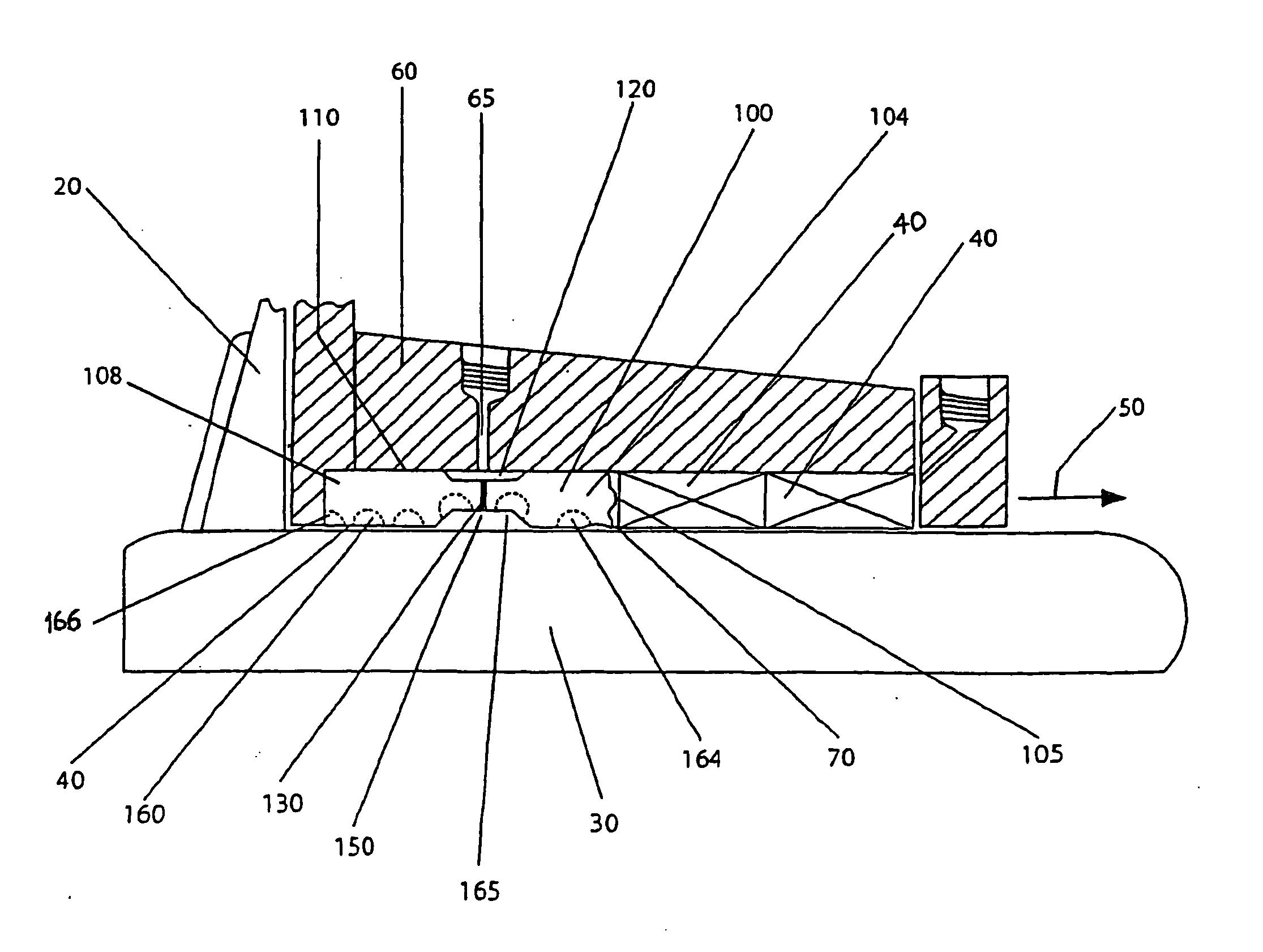
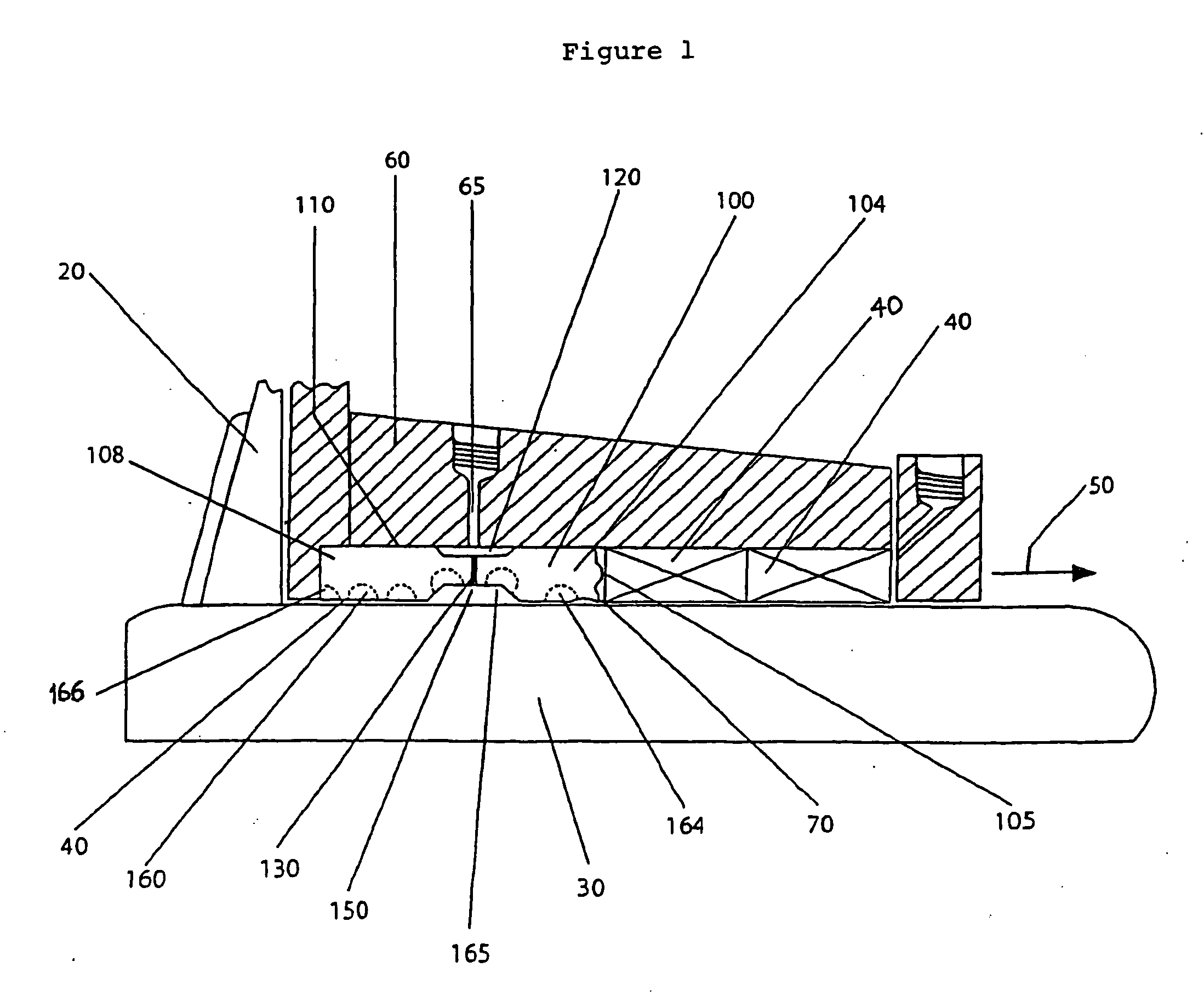
[0047]FIG. 1 depicts a typical environment for a seal cavity throat protector in the form of a bushing according to the present invention which is shown generally at 100. The environment includes an operative portion such as an impeller 20, which is connected to a shaft 30, the shaft 30 being connected to a prime mover such as a motor 40 (not shown). Seals 40 protect bearings which support the shaft which would be further along the shaft in the direction of arrow 50. Shaft 30 together with shaft housing 60 and seals 40 form a seal cavity shown generally at 70.

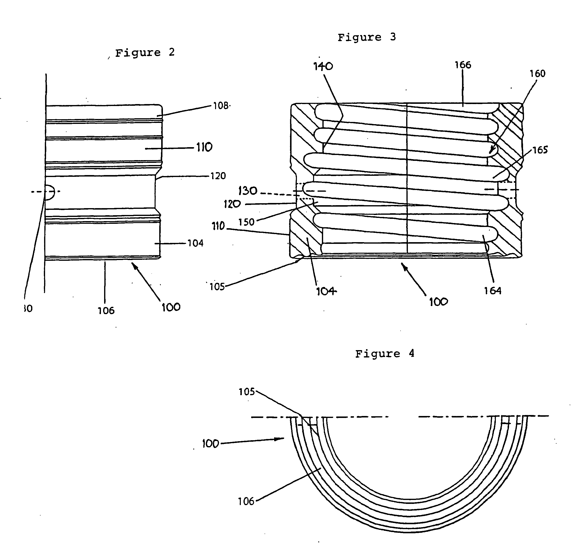
[0048] Bushing 100 has a seal portion 104 adapted to surround the shaft and to engage a seal 40, and an open portion 108 adapted to surround the shaft and to define with the shaft a passageway for ingress and egress of material. Bushing 100 has an outer surface 110 with a circumferential indentation 120, into which a bore 65 through shaft housing 60 empties. Bushing 100 further has a bore 130 which runs from outer surface 110 ...


PUM


Abstract

Rotary shaft (220), housing (250) and packaging type seal (230) together form seal cavity (260). Seal cavity throat protector (200) in cavity (260) protects seal (230) against damaging materials from the region of impeller (210). Such material is directed away from seal (230) along spiral groove(s) (280) on inner surface of protector (200) with the assistance of flushing fluid entering cavity (260) via bore (270) and passing to inner surface of protector (200) via radial bores therethrough.

Description

FIELD OF THE INVENTION [0001] The invention relates to seal cavity throat protectors for use with rotary fluid equipment. BACKGROUND OF THE INVENTION [0002] In this specification, where a document, act or item of knowledge is referred to or discussed, this reference or discussion is not an admission that the document, act or item of knowledge or any combination thereof was at the priority date: [0003] (i) part of common general knowledge; or [0004] (ii) known to be relevant to an attempt to solve any problem with which this specification is concerned. [0005] Rotary fluid equipment usually includes an operative portion such as an impeller which is driven by a prime mover such as a motor. The operative portion usually has a rotating shaft which connects the prime mover to the operative portion. Typically the operative portion is within a housing and the shaft extends through the back of the housing and through a shaft housing. Usually the shaft will be supported by bearings which are ...

Claims


Application Information

Patent Timeline
Patent Type & Authority Applications(United States)
IPC IPC(8): F04D29/10F16J15/18
CPCF16J15/182F04D29/106
Inventor PRINZ, WILHELM
Owner GARLOCK
Why Eureka
Try Eureka