
Heat-resistant clamp device for pipes or similar objects

a technology for pipes and similar objects, applied in the direction of mechanical equipment, other domestic objects, machine supports, etc., can solve the problems of increasing the stress on the cover, difficult to disengage the cover, and requiring a large amount of labor to fasten nuts and bolts to the clamps, so as to save labor on the assembly line, reduce the cost of the clamp device, and strengthen the effect of hard plastic materials

Inactive Publication Date: 2005-12-29
NEWFREY
View PDF9 Cites 34 Cited by
  • Summary
  • Abstract
  • Description
  • Claims
  • Application Information

AI Technical Summary

Benefits of technology

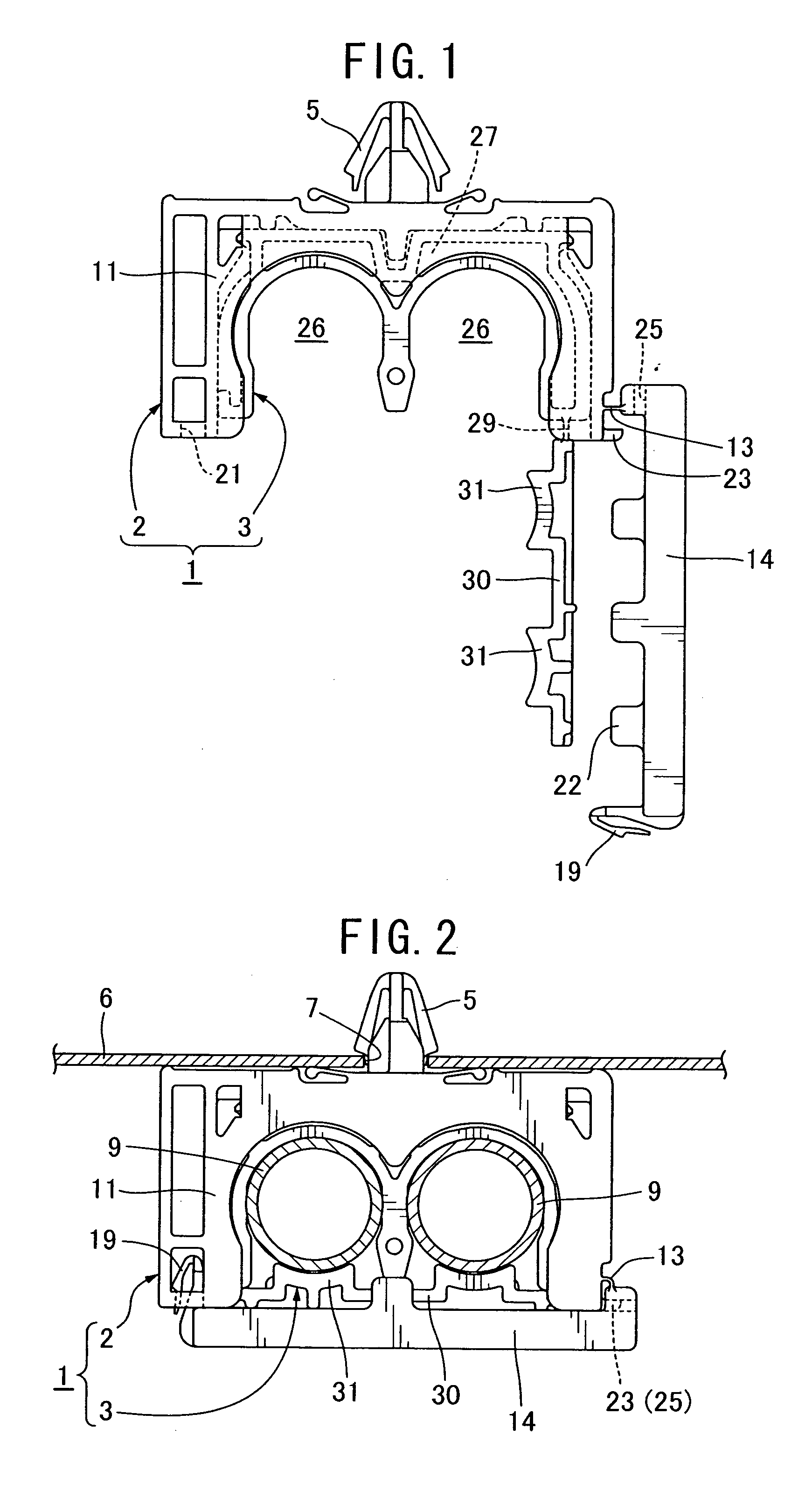
[0009] In this embodiment, an elongated component such as a pipe is held directly by the second clamp made of a hard plastic heat-resistant material. As a result, a high-temperature elongated component such as a heater pipe does not have to be wrapped in a heat-resistant material. Because the first clamp is made of an inexpensive non-heat-resistant hard plastic material, the cost of the clamp device can be reduced and a stronger hard plastic material can be used. The elongated component such as a heater pipe is attached to the second clamp, and the first clamp is mounted holding the second clamp. By transporting the elongated component already attached to the clamp device to an automotive assembly line, labor can be saved on the assembly line.
[0010] In this clamp, the outer peripheral surface of the second clamp is preferably covered by a vibration-resistant elastic plastic covering material layer, and the first clamp preferably holds the second clamp via the covering material layer. This prevents vibrations from being transmitted between the elongated component and the support. When the first clamp holds the second clamp, the elastic material becomes compressed and a reactive force increases the retention strength. In addition, the second clamp can be insert molded with a vibration-resistant elastic plastic material to form a covering layer on the outer peripheral surface of the second clamp. Preferably, the first cover is configured so as to be able to latch the second clamp inside the clamp holder, and the second cover is preferably configured so as to be able to latch the elongated component inside the pipe holder. This improves mounting strength.

Problems solved by technology

When metal clamps are used to mount a high-temperature elongated component such as a heater pipe to a support in an automobile, such as the underfloor, a considerable amount of labor is required to fasten nuts and bolts to the clamps.
When plastic clamps are used, however, the pipe has to be wrapped in a heat-resistant material, called an insulator, to block the transmission of heat from the pipe to the plastic clamps.
When the cover is closed, the rubber mounts are compressed, increasing the stress on the cover and making it difficult for the cover to become disengaged.
Patent Document 1 does not disclose a configuration allowing a high-temperature elongated component such as a heater pipe to be held directly by the clamp.
Patent Document 2 does not disclose a configuration allowing a high-temperature elongated component such as a heater pipe to be held directly by the clamp.

Method used


Image

  • Heat-resistant clamp device for pipes or similar objects
  • Heat-resistant clamp device for pipes or similar objects
  • Heat-resistant clamp device for pipes or similar objects

Examples


Embodiment Construction

[0020] The following is an explanation of a non-limiting example of the present invention with reference to the drawings.

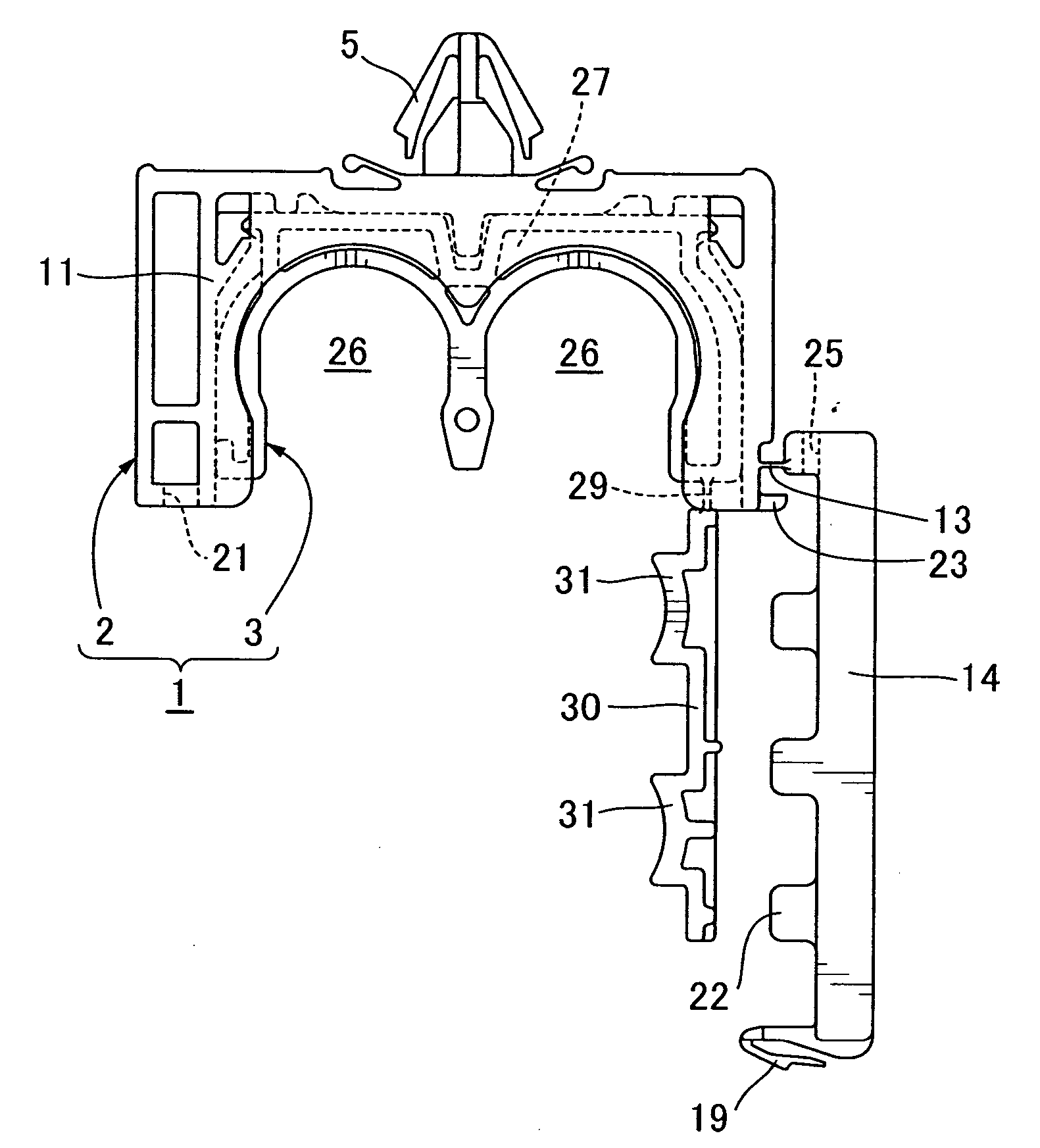
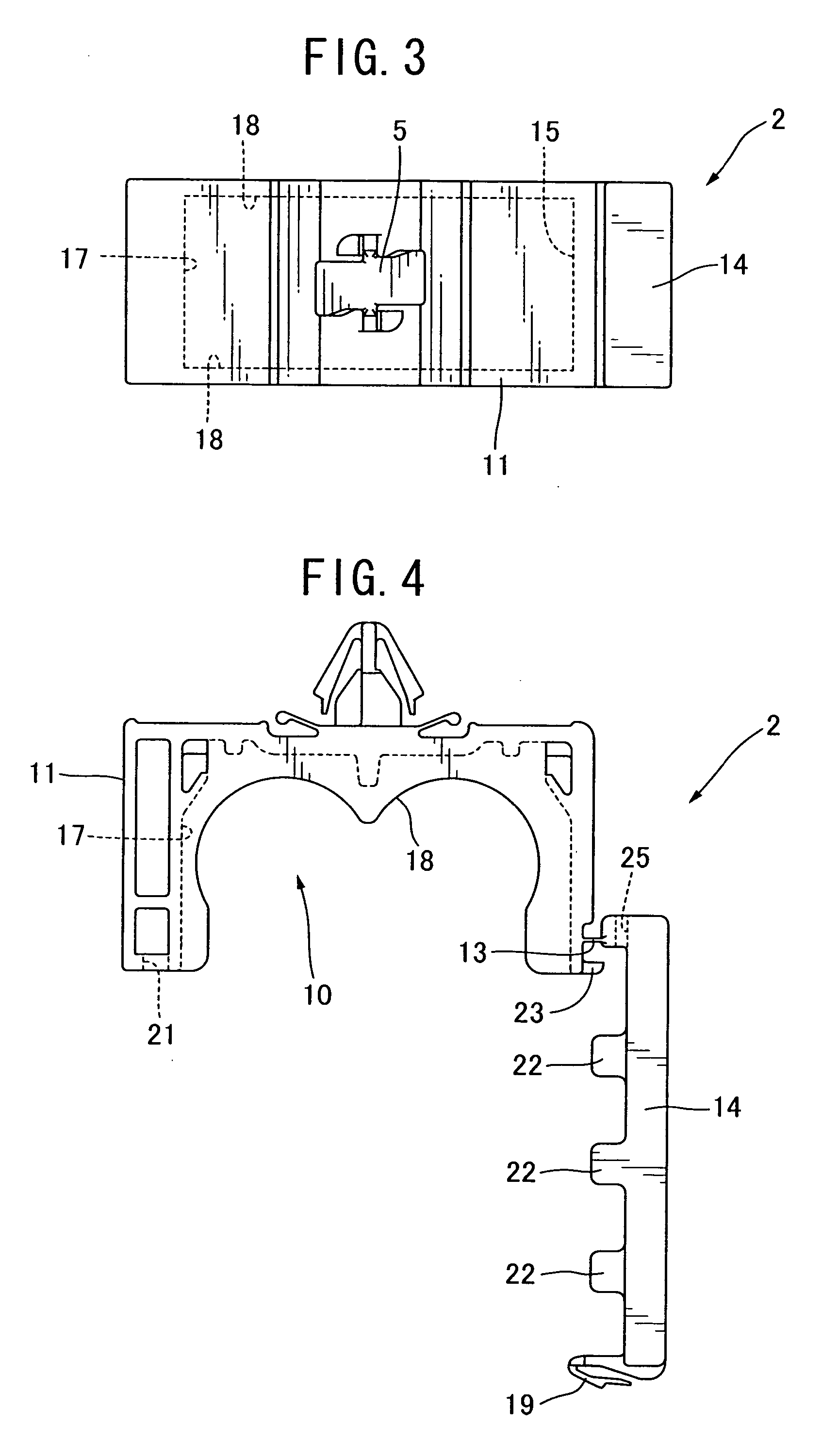
[0021] As shown in FIG. 1 and FIG. 2, a clamp device 1 for a pipe, in according with the present invention, comprises two components: a first clamp 2 and a second clamp 3. Each of the first clamp 2 and the second clamp 3 is preferably a single integral molded plastic product. The first clamp 2 is made of a strong, inexpensive, hard plastic material with non-heat-resistant properties (such as polyoxymethylene or POM). The second clamp 3 is made of a heat-resistant hard plastic material (such as polypropylene or PP) able to hold a high-temperature elongated component such as a heater pipe. The first clamp 2 is fixed by an anchor-shaped mounting device 5 to a support such as the underfloor of an automobile, and also holds the second clamp 3. The mounting device 5 can be some other type. For example, it can comprise a bore for accepting and engaging a standing bolt r...


PUM


Abstract

A clamp device for connecting a high-temperature elongated component to a support comprises a first clamp mountable to the support and a second clamp for holding the elongated component. The first clamp includes a clamp holder for holding the second clamp and is made of a non-heat-resistant hard plastic material. The second clamp includes a holder for holding the elongated component and is made of a heat-resistant hard plastic material. Preferably, the outer peripheral surface of the second clamp is covered by a layer of vibration-resistant elastic plastic material that prevents transmission of vibrations between an elongated component, such as a heater pipe, and a support, such as an under floor of an automobile.

Description

CROSS-REFERENCE TO RELATED APPLICATION [0001] This application claims the benefit of Japanese Application No. 2004-189652 filed Jun. 28, 2004, incorporated herein by reference BACKGROUND OF THE INVENTION [0002] The present invention relates to a heat-resistant clamp device enabling a high-temperature elongated component, such as a heater pipe, to be mounted on a support such as the underfloor of an automobile. [0003] When metal clamps are used to mount a high-temperature elongated component such as a heater pipe to a support in an automobile, such as the underfloor, a considerable amount of labor is required to fasten nuts and bolts to the clamps. Also because metal clamps increase the weight of an automobile, they have increasingly been replaced by plastic clamps. When plastic clamps are used, however, the pipe has to be wrapped in a heat-resistant material, called an insulator, to block the transmission of heat from the pipe to the plastic clamps. A wrapped pipe is fixed to the cl...

Claims


Application Information

Patent Timeline
IPC IPC(8): F16B45/00F16L3/08F16L3/22F16L3/223
CPCF16L55/035F16L3/2235F16L3/12F16L3/222
Inventor MIZUKOSHI, SUGURU
Owner NEWFREY
Learn More