Composite lintel system

Inactive Publication Date: 2005-12-29
SMITH EARL
View PDF9 Cites 25 Cited by
  • Summary
  • Abstract
  • Description
  • Claims
  • Application Information

AI Technical Summary

Benefits of technology

[0029] Thus, an object of the present invention is to provide a lintel structure that is made of composite materials such that it is lightweight compared to prior art lintels, thereby minimizing or preventing sagging of the lintel.
[0030] Another object of the present invention is to provide a lintel structure of the above-described character that is formed of composite materials that have sufficient structural strength to support the brickwork thereon, thereby minimizing or preventing sagging of the lintel.
[0031] Another object of the present invention is to provide a lintel structure of the above-described character that is formed of composite materials and is simple and relatively inexpensive to fabricate.
[0032] Another object of the present invention is to provide a lintel structure of the above-described character that is formed of composite materials having a rigidifying means affixed thereto, thereby minimizing or preventing sagging of the lintel.

Problems solved by technology

A problem with steel angle irons is that they are heavy and that steel bends under a sufficient load.
In fact, the weight of the steel in the angle iron alone will cause it to deform—this sagging is compounded by the additional weight of the brickwork above that is to be supported by the sagging member.
The sagging of the member will cause cracks and weakening of the brick structure above, necessitating eventual replacement of the lintel and brickwork.
The cracks in the brickwork will also cause moisture to enter beneath the brickwork thereby damaging the underlying structure and exposing it to wood infesting insects.
It is another problem with steel angle iron that by its nature, steel (or other metals) will expand and contract due to thermal expansion.
This thermal expansion will inevitable cause such coatings as paint or galvanization to be decimated over time and allow the underlying steel to be exposed to moisture, thereby causing corrosion.
Furthermore, because these coatings are relatively thin, they are easily damaged during shipping and installation of the angle iron.
Furthermore, corrosion of the angle iron creates greater problems.
Accumulation of moisture can cause damage to the underlying wooden or metal structure.
However, some moisture is still retained between the veneer and the structure.
This inevitably leads to corrosion of exposed metal members in the structure, i.e., steel angle irons used as lintels.
Corrosion of the steel lintel can cause diagonal cracks to extend up from the ends of the lintel.
Corrosion that builds up on the top surface of the steel lintel lifts the masonry.
Diagonal cracks form at the ends of the lintel because this area is the weakest plane.
Where there is greater confining pressure, such as at lower levels on a building that does not contain horizontal expansion joints, the pressure generated by the corroding steel causes the portion of the angle above the window to deflect downward and the brick at the jambs to crush.
This is very expensive.
Although the lintel of Welch attempts to provide for a lightweight and rigid member, the device of Welch still does not provide for a corrosion resistant structure.
Although Newman provides a plastic cover for some of the lintel, the device of Newman does not prevent corrosion because portions of the angle iron are still exposed to moisture.
Furthermore, the device of Newman does not provide lightweight of rigidity to the lintel, and thus suffers the disadvantage of sagging under its own weight and that of the bricks thereabove.
Although the lintel of Svensson attempts to provide for a relatively lightweight and rigid member, the device of Svensson still does not provide for a corrosion resistant structure.
Thus, the prior art devices identified above suffer a host of disadvantages.
None of the devices above provide for a lintel structure that is both lightweight yet structurally rigid while also being corrosion resistant.
A plastic cover for only a portion of the steel lintel does not prevent corrosion, and galvanized structures still are not corrosion resistant as the galvanization is easily damaged during transport and installation.

Method used


Image

  • Composite lintel system
  • Composite lintel system
  • Composite lintel system

Examples


Embodiment Construction

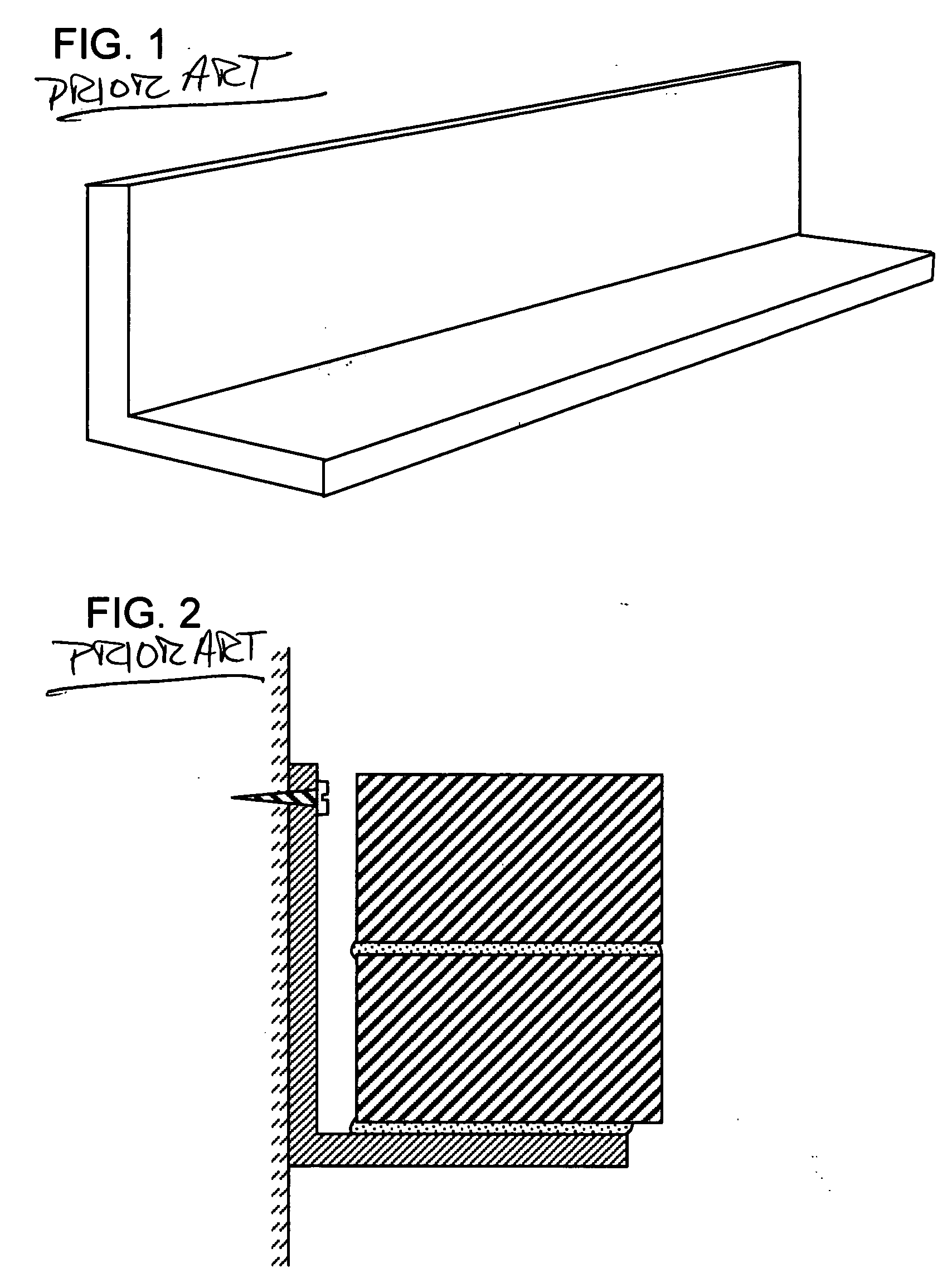
[0057] Referring now to the figures where similar parts are numbered the same throughout. FIG. 1 is a perspective view of a typical embodiment of an angle iron used as a lintel in the prior art. As mentioned herein above, the angle iron typically comprises steel bar having an L-shaped cross-section. FIG. 2 shows the typical configuration of a prior art angle iron affixed to a building structure and having bricks and mortar supported thereon.

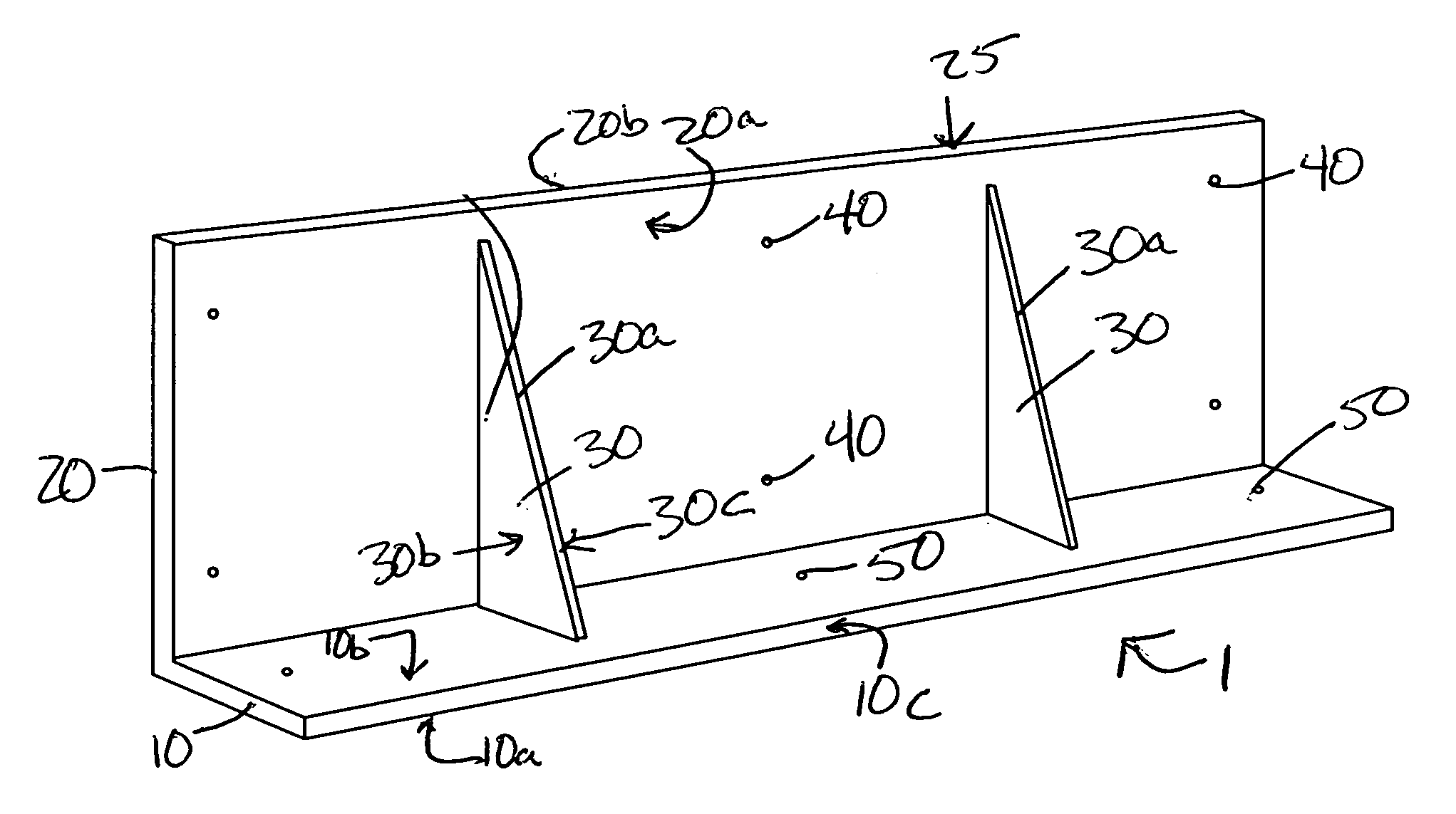
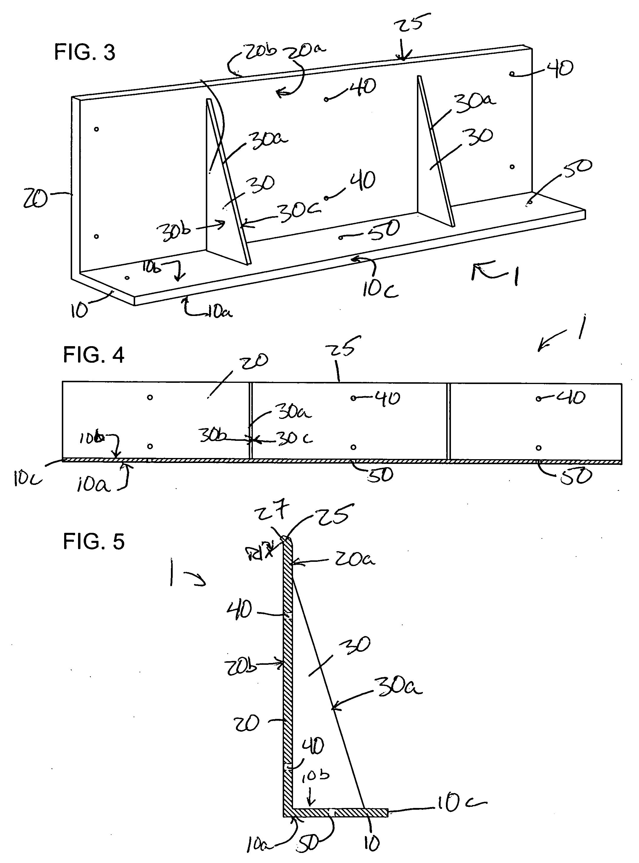
[0058] Referring now to FIGS. 3-5: FIG. 3 is a perspective view of the preferred embodiment of the invention. In this embodiment, the lintel 1 comprises a composite structure having a generally L-shaped cross-section. The lintel 1 has a vertical leg 20 which is affixed to the underlying structure (building header or frame above the opening) and which is rigidly attached to a horizontal leg 10, upon which bricks and mortar are laid.

[0059] The materials of construction of the vertical leg 20 and horizontal leg 10 of the lintel 1 are preferably co...


PUM


Abstract

A composite lintel structure is disclosed for spanning openings in a building structure and for supporting building materials thereon. The composite lintel structure has a vertical leg for affixation to a building structure and a horizontal leg for placement of one or more courses of building materials thereon. The materials of construction of the lintel structure are preferably selected from composites that are moisture impermeable and corrosion resistant. The lintel structure may also comprise one or more stiffeners rigidly or adjustably attached between the horizontal and vertical legs to accommodate load transference from the horizontal leg to the vertical leg of the lintel structure.

Description

BACKGROUND OF THE INVENTION [0001] 1. Field of the Invention [0002] The present invention relates to a lintel system for supporting bricks and other veneers above openings in a building structure. More specifically, the present invention comprises a composite lintel that is lighter and more corrosion resistant as compared to conventional steel lintels. The lintel has a variety of configurations to accommodate various areas of a building structure that require the use of a load bearing support member. [0003] 2. Description of the Prior Art [0004] Brick and concrete structures are common in the prior art. Many structures are built from brick, concrete and the like because of their many advantages including: durability and strength; fire resistance; temperature and sound insulation; general attractiveness; and ease of maintenance, i.e., elimination of the rotting, denting, warping, rusting, splitting, peeling, and fading associated with wooden structures, as well as a deterrent to wood...

Claims


Application Information

Patent Timeline
IPC IPC(8): E04C3/02E04C3/29E04C3/38
CPCE04B1/7046E04C3/02E04C2003/023E04C3/38E04C3/29
Inventor SMITH, EARL
Owner SMITH EARL
Why Eureka
Try Eureka