
Rimless eyeglasses and parts thereof

a technology of eyeglasses and parts, applied in the field of rimless eyeglasses, can solve the problems of inability to tightly fasten the lenses “a” and their associated parts, the metal molds used for pressing and shaping minute objects are very expensive, and achieve the effect of convenient assembly

Inactive Publication Date: 2005-12-15
INADA PROJECT
View PDF1 Cites 60 Cited by
  • Summary
  • Abstract
  • Description
  • Claims
  • Application Information

AI Technical Summary

Benefits of technology

[0009] In view of the above one object of the present invention is to provide a rimless eyeglasses whose parts can be easily assembled without soldering.
[0010] Another object of the present invention is to provide a bridge and a joint piece which assures that the eyeglasses is free of loosening in its temples and / or bridge.
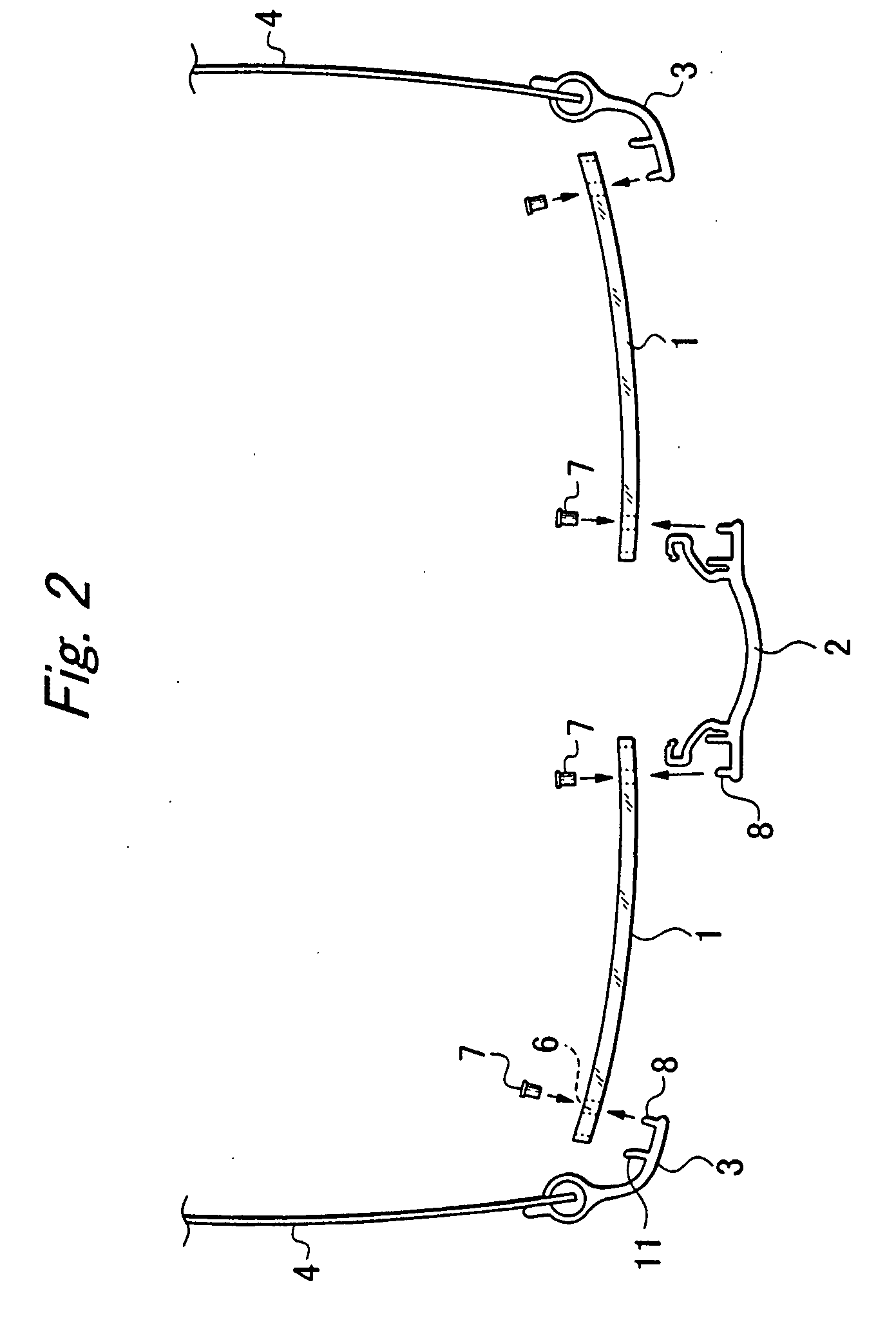
[0014] Then, the saw-tooth indentations of the pin-like extension cut into the inside of the flanged sleeve to be fixedly caught. The flanged sleeve is expanded by forcedly inserting the pin-like extension in the flanged sleeve, thereby making it stick to the hole. The pin-like extension is formed by punching a piece of metal sheet, and therefore its cross section is rectangular. The pin-like extension comes to contact with the circular hole at the four corners, leaving arc spaces between the four sides of the square pin and the circular hole. This permits smooth insertion of the pin-like extension into the hole thanks to minimum friction. Square holes, however, may be made in the lens.
[0015] The bridge is fastened to the lenses with its pin-like extensions inserted in the flanged sleeves in the lens holes next to the bridge, and likewise, the joint pieces are fastened to the lenses with their pin-like extensions inserted in the flanged sleeves in the lens holes next to the joint piece. To prevent any relative rotation around each pin-like extension the bridge and joint pieces are fastened to the lenses with their press-fitting extensions inserted in the notches of the lenses. Alternatively the press-fitting extension may be so shaped in the form of letter “U” to pinch periphery of the lens. The angular rotation can be prevented by applying such press-fitting extensions to the lenses.

Problems solved by technology

If the screws “g” are loosened, however, the lenses “a” and associated parts “b” and “c” cannot be tightly fastened together even though the anti-rotary pieces “f” are applied to the outer circumferences of the lenses “a”.
Metal molds for pressing and shaping minute articles are very expensive.
Screwing such minute parts to lenses is a tedious and time-consuming work.
Disadvantageously the bridge “b” and its opposite legs “e” cannot be pressed and shaped as a whole.
The hinge structure has similar problems.
It is so small that it cannot be made with ease, and hinging the temple “d” to the joint piece “c” is a tedious and time-consuming work.
Still disadvantageously, the temple “d” is apt to wear on the parts at which it is rubbed against the hinge; the friction against the temple wears it.
The assembling and soldering of parts into the joint piece and the bridge cannot assure that these articles be provided with precision.
As a result, they cannot be always exactly aligned with the minute holes made in the lens “a”.
Such misalignment, in fact, causes loosening the temple and / or joint pieces relative to the lens, and what is worse is to prevent parts from being assembled into eyeglasses.

Method used


Image

  • Rimless eyeglasses and parts thereof
  • Rimless eyeglasses and parts thereof
  • Rimless eyeglasses and parts thereof

Examples


Embodiment Construction

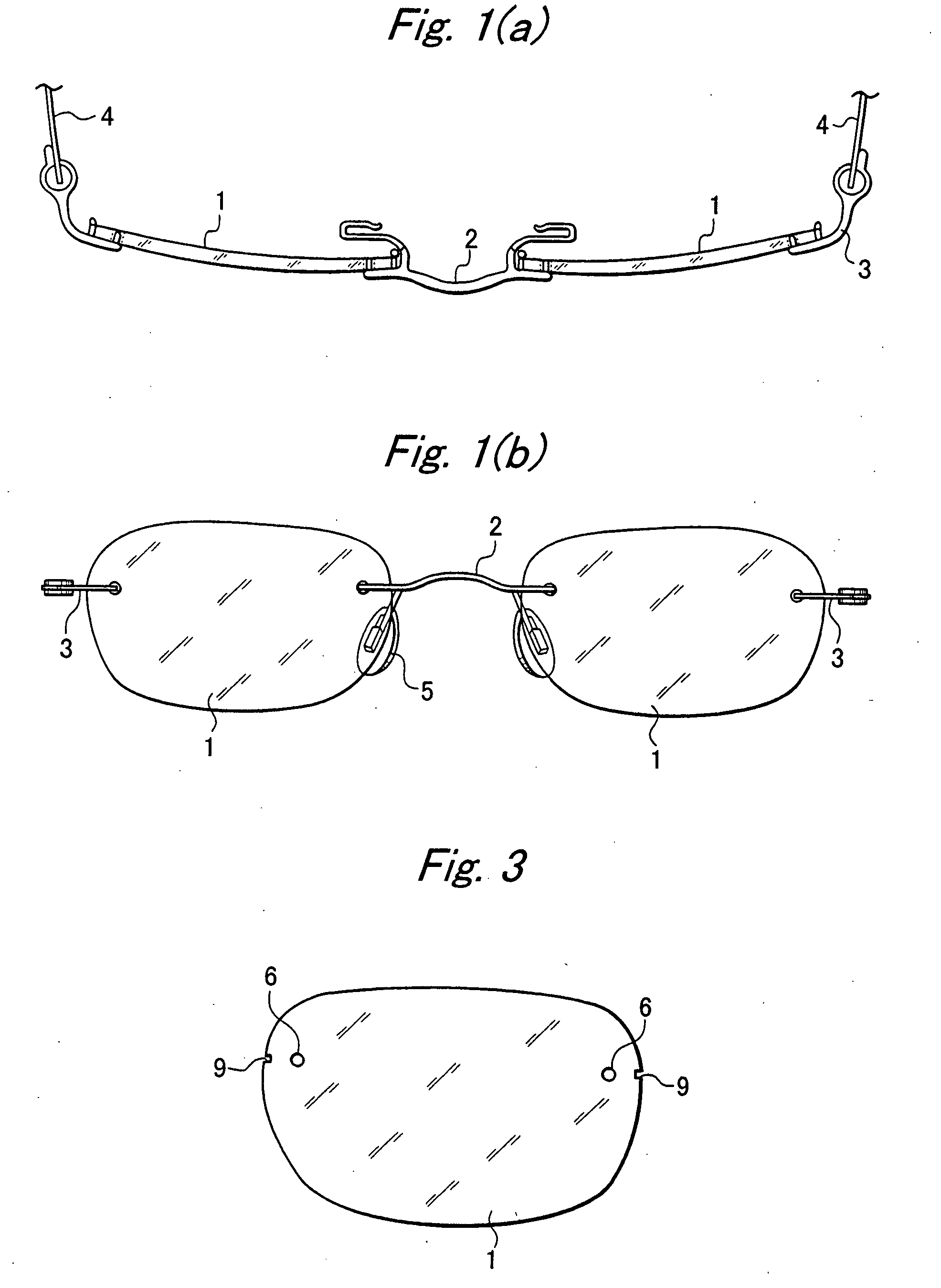
[0038] Referring to FIGS. 1a and 1b, a rimless eyeglasses according to one preferred embodiment of the present invention comprises two lenses 1, a bridge 2 whose opposite ends are connected to inner edges of the two lenses 1, two joint pieces 3 fixed to the outer edges of the two lens 1, and two temples 4 hinged to the joint pieces 3. As shown, the bridge 2 has two legs integrally connected to its opposite ends, and each leg has a nose pad 5 attached to its end. Referring to FIG. 4, the bridge 2 is shaped by cutting or punching a piece of metal sheet into a required flat shape (FIG. 4a), comprising a crossbar 10 having two pin-like extensions 8, two press-fitting extensions 11 and two leg extensions 12, all integrally connected to the opposite ends of the crossbar 10. The pin-like extensions 8 have saw-tooth indentations formed on their opposite sides, and the leg extensions 12 end with hooks 13 for fixedly holding nose pads 5. The flat shape of bridge (FIG. 4a) is bent into the thr...


PUM


Abstract

To manufacture a rimless eyeglasses without soldering the parts easily and make the assembling easy, a bridge and two joint pieces are provided by cutting or punching a piece of metal sheet into a required flat shape. The bridge comprises a crossbar having two pin-like extensions, two press-fitting extensions and two leg extensions integrally connected to the opposite ends of the crossbar. The pin-like extensions have saw-tooth indentations formed on their surfaces, and the leg extensions end with hooks for fixedly holding nose pads. Each joint piece has a pin-like extension with saw-tooth indentations formed on its surface and a press-fitting extension. Each lens has a through hole and a notch made on either side. Each through hole has a flanged sleeve press-fitted therein, and the pin-like extensions of the bridge and joint pieces are inserted into the flanged sleeves in the through holes of the lenses, and the press-fitting extensions of the bridge and joint pieces are inserted into the notches of the lenses.

Description

BACKGROUND OF THE INVENTION [0001] 1. Field of the Invention [0002] The present invention relates to rimless eyeglasses whose lenses are directly connected to each other and to the temples without rims, and to the hinge structure for the temples. [0003] 2. Related Art [0004]FIG. 20 shows ordinary rimless eyeglasses. As shown, both lenses “a” are connected to each other by screwing to a bridge “b”. Each lens “a” has a joint piece “c” screwed to its outer edge, and a temple “d” is foldably hinged to the joint piece “c”. The bridge “b” has nose pads “e” fixed to its leg ends. [0005] As described, the bridge “b” is fastened to the lenses “a” with minute screws “g”, and likewise, the joint pieces “c” are fastened to the lenses “a” with minute screws “g”. To prevent angular rotation of the bridge or joint piece about a single screw “g”, the bridge and joint piece are equipped with anti-rotary pieces “f”, thereby preventing the bridge and joint pieces from turning, and assuring they stick ...

Claims


Application Information

Patent Timeline
IPC IPC(8): G02C1/00G02C1/02
CPCG02C1/02
Inventor YAMAGUCHI, JITSUKOYAMAGUCHI, KATSUSHI
Owner INADA PROJECT
Learn More