Mechanical joint gripping gasket

Inactive Publication Date: 2005-12-15
STAR PIPE PRODS
View PDF20 Cites 13 Cited by
  • Summary
  • Abstract
  • Description
  • Claims
  • Application Information

AI Technical Summary

Benefits of technology

[0009] In one aspect, the present invention provides a retention and sealing device for mechanical joints between tubulars. In one embodiment, the sealing device is a gasket is used to join a first tubular having a socket end with a second tubular having a spigot end. The gasket is compressed within the joint by a gland that is connected by fasteners to the socket end. The exemplary device includes a resilient annular member having a sealing portion for forming a seal between the first tubular and the second tubular and at least one gripping element positioned in the resilient member. The gripping element includes a plurality of teeth projecting radially inward relative to the socket for gripping an outer surface of the spigot end and a blunt nose extending axially forward relative to the socket for contacting a front wall of the gland. The gripping element can also include wings extending from the gripping element that enhance stability and effectiveness of the gripping element and a radially outward knob that limits the radial travel of the blunt nose. The blunt nose adapted to contact and roll along the front wall during relative movement between the first and second tubulars. The terms radially inward(ly) and radially outward(ly) are used with reference to the axial centerline of the tubulars (i.e., meaning pointing toward or away from the tubular centerline, respectively). The terms axially forward refers to a direction toward the end of the tubular and term axially rearward refers to a direction toward the middle of the tubular.
[0011] In embodiments, the gripping element can also include arrangements to enhance the locking function provided by the gripping elements, facilitate assembly, improve product life and improve performance, etc. For instance, the gripping element can include least four teeth arranged such that no more than two teeth grip the outer surface of the spigot end when the spigot end is inserted into the socket end. For instance, at least three can lie along a common arc. Additionally, the gripping element can include a ridge extending radially outwardly from the gripping element to limit the movement of the blunt nose along the front face. In certain embodiments, at least one tooth includes a transverse groove that enhances the tooth's ability to penetrate into the outer surface of the spigot.

Problems solved by technology

The ability of the gasket to seal and lock the joint, however, can be adversely affected by such dimensional variations.
Moreover, there is a persistent need for gaskets that lock or retain a joint without unduly compromising the structure of the pipe (e.g., excessive penetration).

Method used


Image

  • Mechanical joint gripping gasket
  • Mechanical joint gripping gasket
  • Mechanical joint gripping gasket

Examples


Embodiment Construction

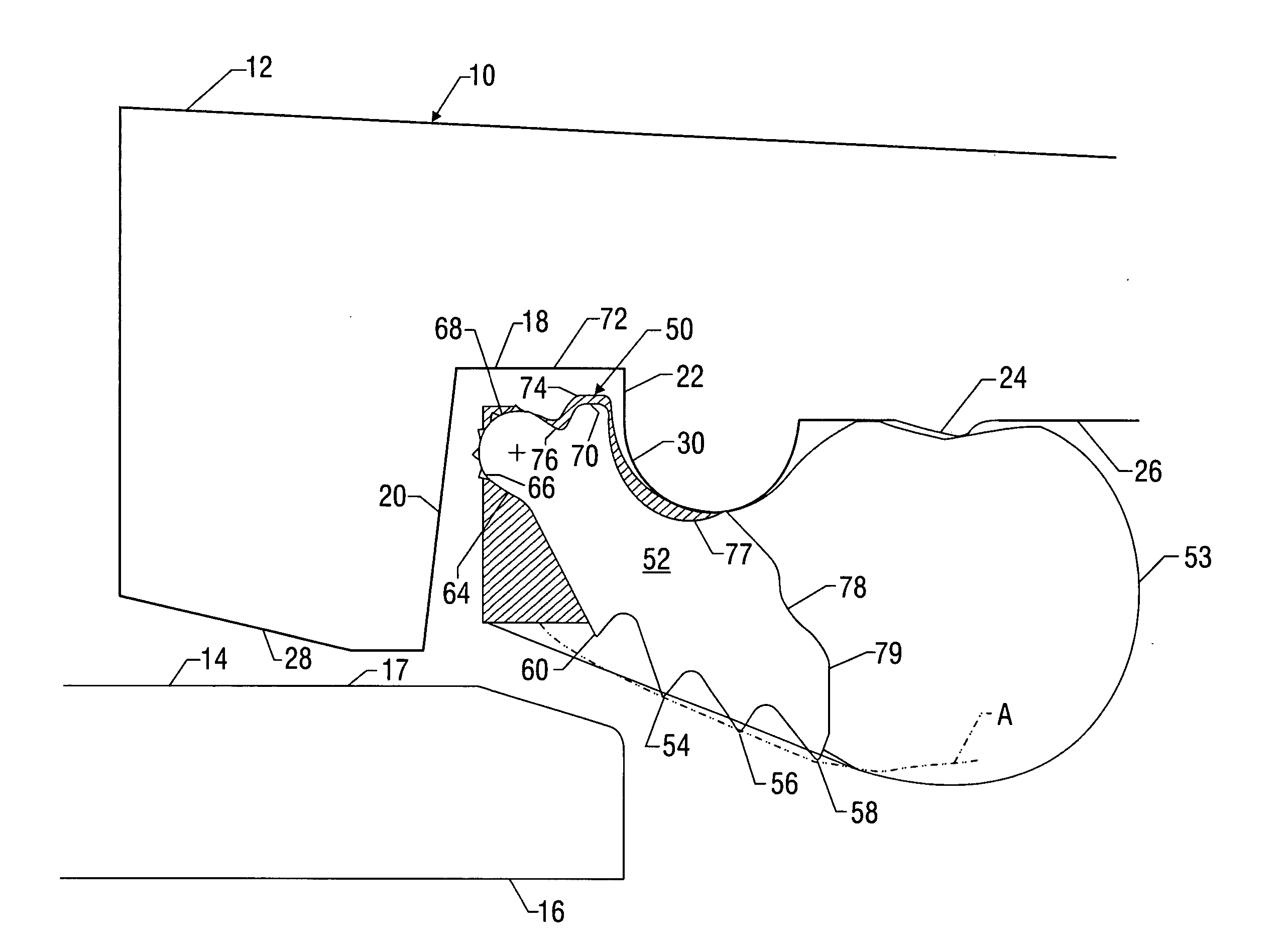
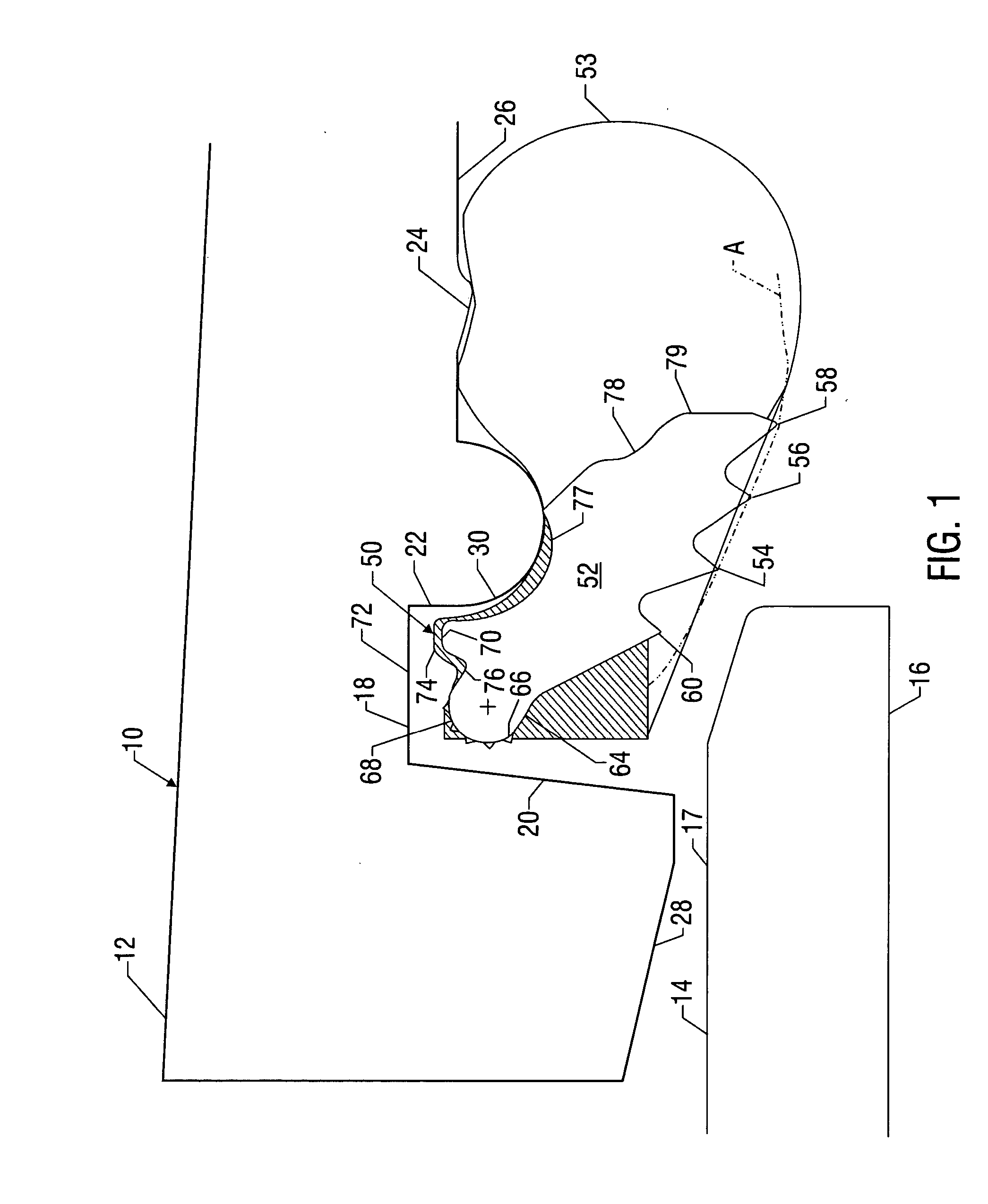
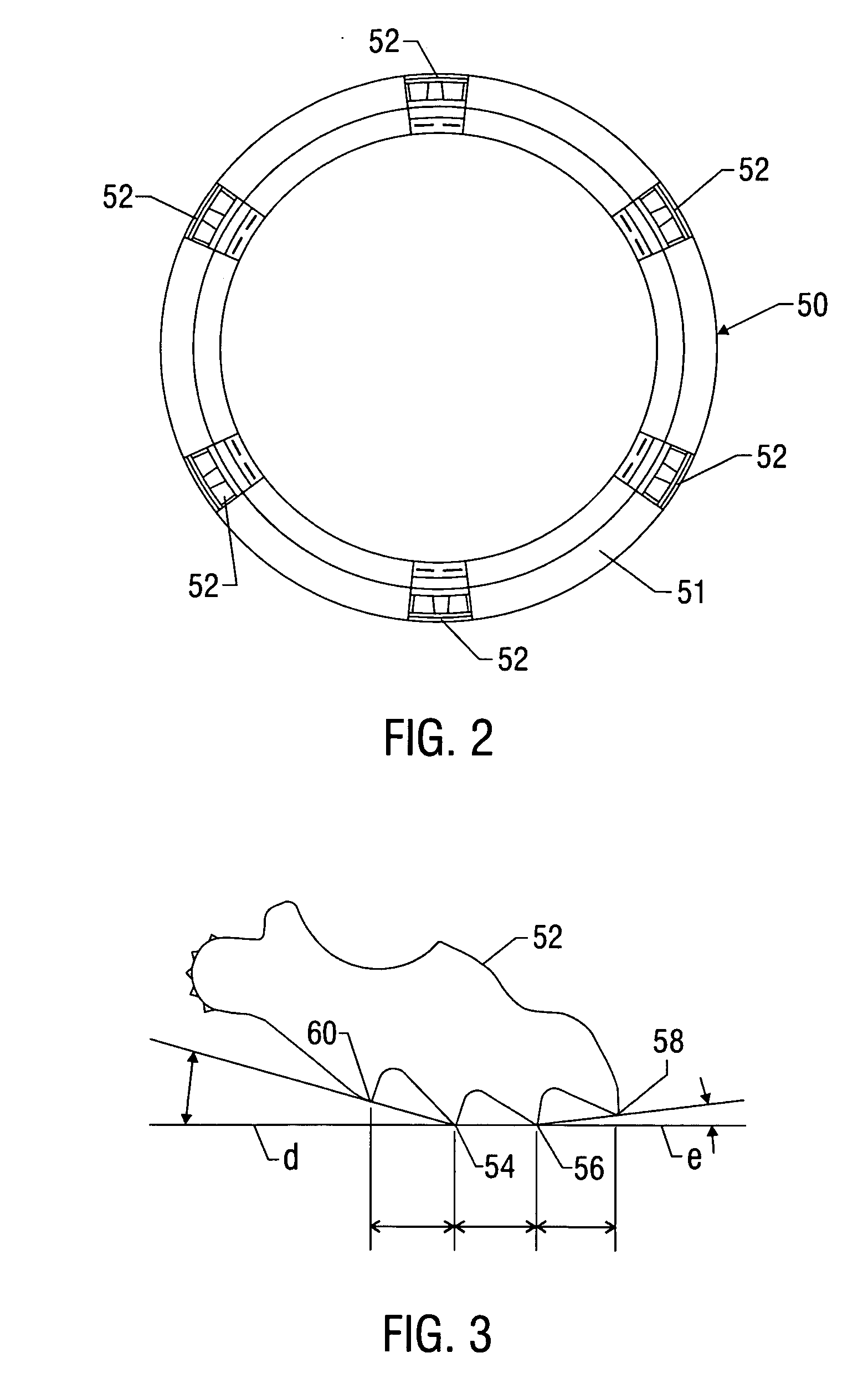
[0024] The present invention relates to devices and methods providing robust and cost-effective gasket arrangements for pipe joints. The present invention is susceptible to embodiments of different forms. There are shown in the drawings, and herein will be described in detail, specific embodiments of the present invention with the understanding that the present disclosure is to be considered an exemplification of the principles of the invention, and is not intended to limit the invention to that illustrated and described herein. As used herein, the terms radially inward(ly) and radially outward(ly) are used with reference to the axial centerline of the tubulars (i.e., meaning pointing toward or away from the tubular centerline). The terms axially forward means in a direction toward the end of the tubular and term axially rearward means in a direction toward the middle of the tubular. Further, no particular geometry, material, or other technical limitation is implied by the term “gas...


PUM


Abstract

A novel gasket includes at least one gripping element embedded in an annular member for forming a seal between two tubulars. For tubulars having socket and spigot ends, the gripping element includes teeth for gripping an outer surface of the spigot end and a blunt nose for contacting a front wall of a gland that compresses the gasket against surfaces of the socket and spigot ends. The blunt nose rolls along the front wall of the gland during relative movement between the tubulars and can include a contacting face of a specialized geometry to adjust contact dynamics and / or roughened surfaces to increase the frictional contact between the blunt nose and the front wall. The gripping elements can also include at least four teeth arranged such that no more than two teeth normally grip the outer surface of the spigot end. One or more teeth can also include a transverse groove to enhance penetration into the outer surface of the spigot end.

Description

CROSS-REFERENCE TO RELATED APPLICATIONS [0001] This is a continuation-in-part of U.S. patent application Ser. No. 10 / 817,674, filed Apr. 2, 2004.BACKGROUND OF THE INVENTION [0002] 1. Field of the Invention [0003] This invention relates to devices for locking joints for tubular members. More particularly, the present invention relates to gaskets for sealing and locking a socket end of one tubular to a spigot end of another tubular. [0004] 2. Description of the Prior Art [0005] Pipes joined in telescoping relationship typically have a spigot end of one pipe inserted into the socket end of the engaging pipe. The socket end has an opening large enough to receive the spigot end of the enclosed pipe. A gasket is inserted in the socket end of the enclosing pipe and prevents leakage of fluid from the joint by forming a seal between the two pipes. In many applications, a fluid under pressure flows through the pipes. This fluid pressure can produce a separating force, known as joint separatin...

Claims


Application Information

Patent Timeline
IPC IPC(8): F16L17/00F16L21/02F16L21/08F16L27/08F16L37/084
CPCF16L37/0845
Inventor WALWORTH, VAN T.HOOK, DAVID B.
Owner STAR PIPE PRODS
Why Eureka
Try Eureka