Myopia correction enhancing biodynamic ablation

a biodynamic ablation and myopia technology, applied in the field of laser vision correction, can solve the problems of reducing the oz size, glare and halo effects in low-light conditions, and achieve the effects of reducing the ablation depth of corneal tissue, reducing the amount of tissue ablation, and increasing the optical zone siz

Inactive Publication Date: 2005-12-08
TECHNOLAS OPHTHALMOLOGISCHE SYST
View PDF9 Cites 15 Cited by
  • Summary
  • Abstract
  • Description
  • Claims
  • Application Information

AI Technical Summary

Benefits of technology

[0010] An embodiment of the invention is directed to a method for a LASIK or a LASEK myopia (with or without astigmatism) laser vision correction, including the control and improvement thereof. The method generally relies on a corneal biodynamic effect to reduce the amount of tissue ablation, i.e., ablation depth, as a function of increased optical zone size. According to the invention, a corneal biodynamic effect is induced which results in a flattening of the central corneal region, By flattening the cornea in a controlled manner, a shallower myopia correcting ablation can be performed over an optical zone area than would occur over the same optical zone area if the cornea were not flattened from its original shape. In a preferred aspect, the trauma inflicted to the eye is a biodynamic ablation in the form of at least one or more portions of, or a complete, ring or annulus. The biodynamic ring may be circular or non-circular (i.e., elliptical or other shape). In this aspect, the ring or annulus of ablated corneal tissue is outside of and surrounding the optical zone. The parameters of the biodynamic ring, particularly the distance from the optical zone edge, and the width and depth of the ring, all of which are variable as a function of biodynamic ablation location, will produce a controlled biodynamic effect that will be advantageous for reducing the ablation depth of corneal tissue in the optical zone to effect a myopia correction.

Problems solved by technology

One solution is to decrease the OZ size; however, one cause of post-LASIK spherical aberration resulting in glare and halo effects in low-light conditions is believed to be due to an ablated OZ that is smaller than the patient's pupil in low light conditions.

Method used


Image

  • Myopia correction enhancing biodynamic ablation
  • Myopia correction enhancing biodynamic ablation
  • Myopia correction enhancing biodynamic ablation

Examples


Embodiment Construction

[0021] The invention is directed to a method for a LASIK or a LASEK myopia (with or without astigmatism) laser vision correction, and to a computer or device readable medium having stored therein an executable instruction or instruction code for directing an ophthalmic vision correcting laser platform to perform a myopia correction enhancing biodynamic ablation according to an embodiment of the invention.

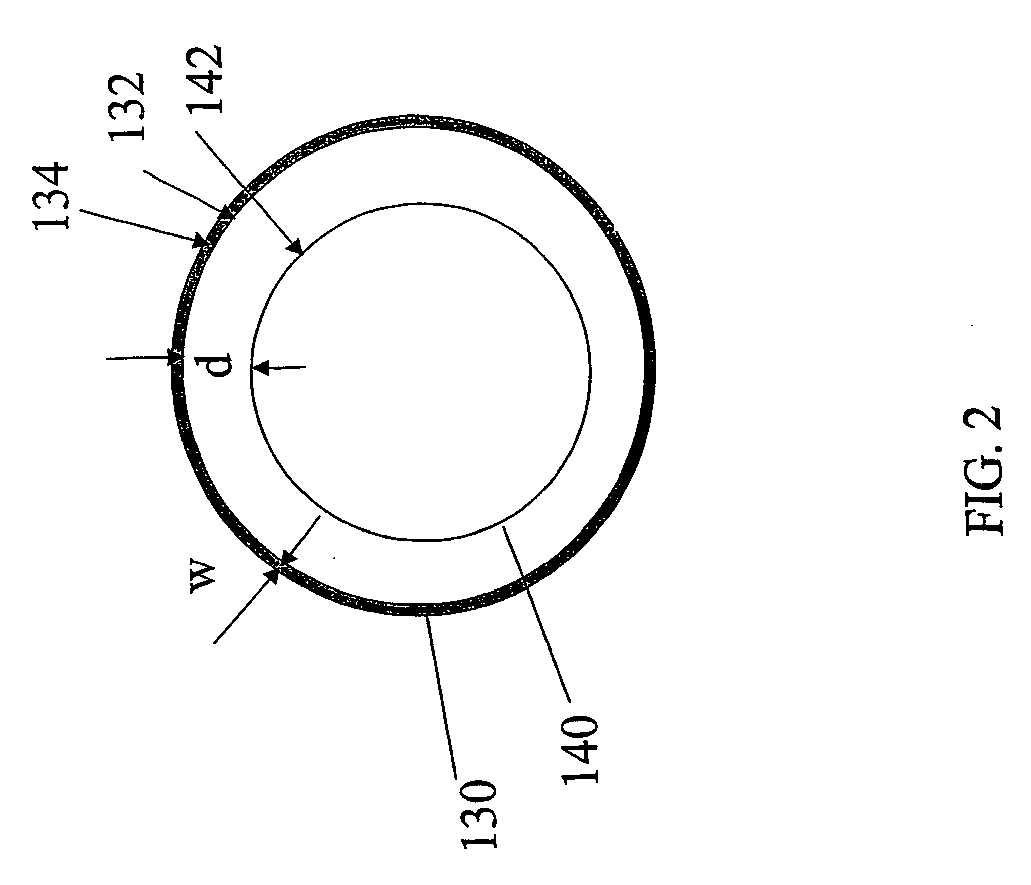
[0022]FIG. 1 schematically shows a front view of an eye 100 including an optical zone (OZ) 140 of the eye, and the outer boundary 110 of the iris of the eye. When LASIK or LASEK corrective surgery is performed on an eye, the actual vision correcting ablation which is referred to herein as the nominal ablation, is typically performed over a region of the pupil (dilated or undilated) referred to as the optical zone 140. A transition zone 120 typically lies outside of and immediately adjacent to the optical zone and defines a boundary between the ablated and non-ablated areas of the c...


PUM


Abstract

This invention is directed to a method for providing a LASIK or a LASEK myopia vision correction, and to a medium that has stored therein an instruction for directing a laser vision correcting laser platform to deliver a controlled biodynamic ablation according to the invention. A known biodynamic response of the eye is induced by performing a controlled laser ablation in a cornea of the eye outside of an optical zone for the nominal ablation in a laser vision correction surgery. An ablation ring, or portion thereof, outside of the optical zone produces a biodynamic flattening of the central region of the cornea which in turn provides for a decreased depth of volumetric ablation to correct a myopic refractive defect of the eye. Such controlled biodynamic flattening may provide the opportunity for laser vision correction in patients whose corneas would otherwise be too thin post-operatively to warrant laser vision correction.

Description

BACKGROUND OF THE INVENTION [0001] 1. Field of the Invention [0002] The invention is generally directed to the field of laser vision correction and, more particularly, to a method and device for inducing and utilizing a corneal biodynamic effect for improving laser vision correction. [0003] 2. Description of Related Art [0004] The field of laser vision correction currently offers several types of procedures for correcting or improving refractive defects by laser photoablation of the corneal surface. These procedures include PRK, LASIK, and LASEK, which are typically used to correct myopic and hyperopic defects with or without astigmatism, and in some cases provide customized treatments to address the higher order aberrations of the eye. [0005] The evolution of laser technology and its use in the vision correction field has contributed significantly to the state of the art of laser vision correction. Ten years ago, broad-beam lasers utilizing variable diaphragms and / or masks were use...

Claims


Application Information

Patent Timeline
IPC IPC(8): A61B18/20A61F9/007A61F9/01
CPCA61F9/008A61F9/00804A61F9/00817A61F2009/00857A61F2009/00872
Inventor YOUSSEFI, GERHARDMORITZ, FRIEDRICH
Owner TECHNOLAS OPHTHALMOLOGISCHE SYST
Why Eureka
Try Eureka