Connector

Inactive Publication Date: 2005-12-08
ONG CHIN CHAI
View PDF13 Cites 23 Cited by
  • Summary
  • Abstract
  • Description
  • Claims
  • Application Information

AI Technical Summary

Benefits of technology

[0015] It is a feature of the invention that when a load is applied to a pair of interengaged connectors, portions of an inner face of one connector engage with opposed portions of an outer face of the other connector and vice versa to cause the connectors to bindingly lock against each other to prevent disconnection. The engagement of portions of the inner face of one connector with opposed portions of the outer face of the other connector under the tensile load causes deformation of the connectors to increase the degree of engagement between the opposed inner and outer faces which serves to further resist separation of the connectors.

Problems solved by technology

Numerous difficulties may be encountered during manufacture and / or assembly of many existing types of sheet piling.
One such difficulty may arise during driving.
The end of the pile being driven may encounter changes in earth hardness or inclusions such as rocks and pebbles, which can cause it to deflect, thereby subjecting the connection it forms with the adjacent sheet pile to complex loading.
Such loading may be in directions the connection is not equipped to cope with.
This problem in particular may be encountered where the sheet piles have been cold rolled because such sheet piles can be provided only with relatively simple shaped connectors able to permit substantially unidirectional loading.
Loading of the connectors of sheet piles in a direction with which they are not equipped to cope, particularly during driving, can cause the connections to jam.
Where the loading is sufficiently high, the connectors may fail, by unhooking and / or deformation, thus causing the sheet piles to become disconnected.
The need for more than one type of cold rolled sheet pile thus creates manufacturing complexity.
Also, the abovementioned risks of jamming and disconnection during driving remain.
The requirement that these clutch sections be separately hot rolled represents a significant drawback because of the very high production costs associated with hot rolling.
Hot rolling requires complex and extremely expensive plants and infrastructure.
It is therefore not economical to produce hot rolled items in small volumes.
Furthermore, the need to manufacture the clutches separately and then fix them to the sheet pile side walls introduces manufacturing complexity and further expense.

Method used


Image

  • Connector
  • Connector
  • Connector

Examples


Embodiment Construction

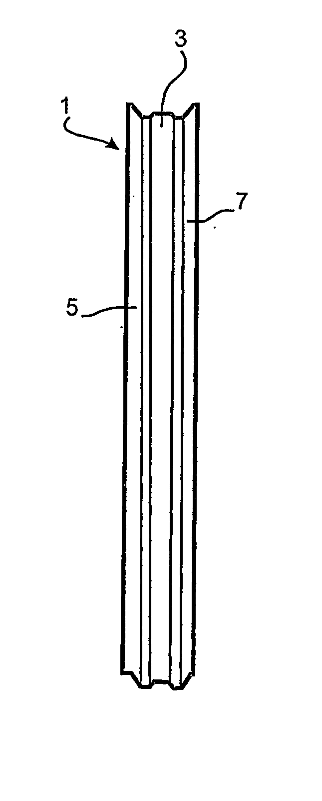
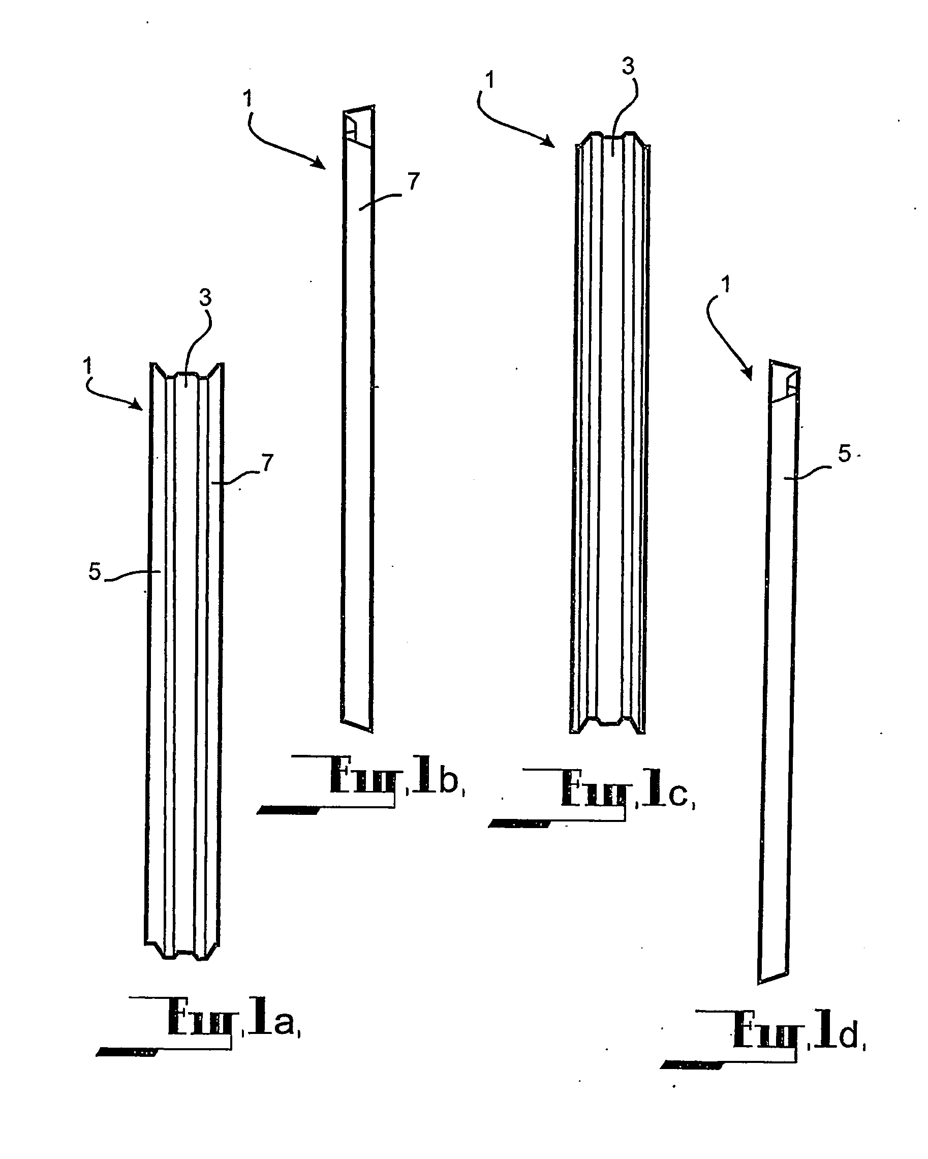
[0053] The panel according to the specific embodiment is a sheet pile 1, generally shown at FIGS. 1A to 1D, and in particular a thin walled sheet pile. The sheet pile 1 according to the embodiment is formed of a resiliently flexible material and, in particular, cold rolled from metal plate such as mild steel plate.

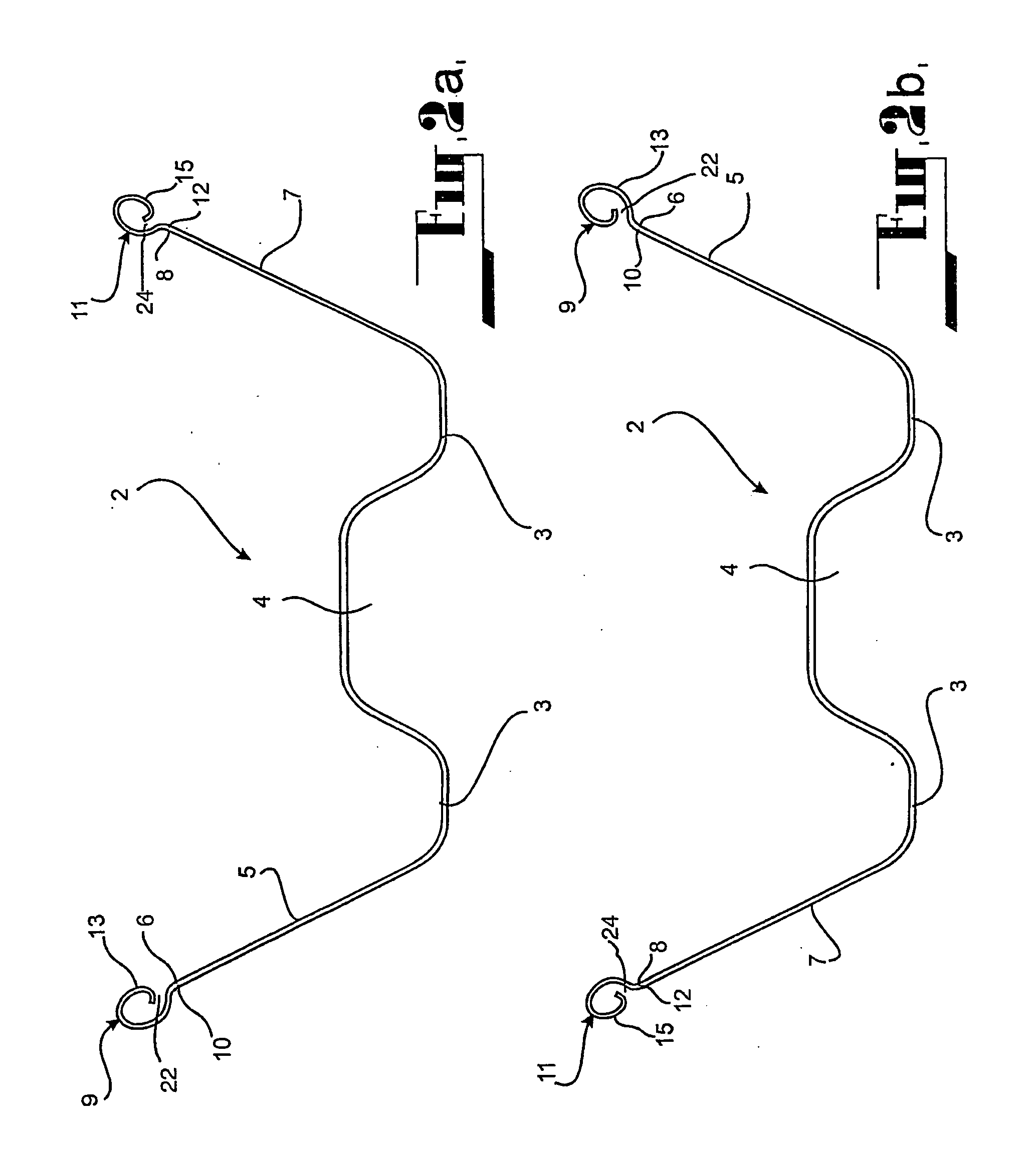
[0054] The sheet pile 1 according to the embodiment comprises a main body in the form of a channel section. The main body 2 (shown at FIGS. 2A and 2B) comprises a web 3 and opposed flanges 5 and 7 extending from the web to edges 6 and 8 respectively. The flanges 5 and 7 diverge from the web 3 to give the main body 2 a generally W-shaped configuration and thus to afford the sheet pile 1 increased transverse stiffness.

[0055] The edges 6 and 8 of the main body 2 according to the embodiment are substantially parallel.

[0056] In this embodiment, a middle portion of the web 3 is offset from the general plane of the web in the direction of the main body 2 to form a corrugation ...


PUM


Abstract

A panel connector for interconnecting adjacent panels, wherein the panels have one or more flanges each having an edge. The connector comprises a portion of sheet material arranged to extend from the edge of the panel with a curved profile having an inner end adjacent the edge of the panel and an outer end. In transverse cross section, the curved profile includes a first portion extending from the inner end in a generally elliptical path and a second portion extending from the first portion to the outer end. The second portion curves inwardly from the generally elliptical path and the curved profile of the connector curves through at least 360 degrees. The second portion defines an opening between the inner end and the outer end to receive a portion of a further connector on an adjacent panel of the same shape.

Description

FIELD OF THE INVENTION [0001] This invention relates to a panel connector, a panel incorporating such a connector and an assembly of such panels. [0002] The invention has been devised in particular, though not necessarily solely, for sheet piling to facilitate interconnection of sheet piling elements to form a sheet piling assembly. BACKGROUND ART [0003] A sheet pile's main function is to withstand sideways loading. Sheet piles are thus used to form retaining walls in various applications, including basement excavations, underground car parks, and cofferdams. Sheet piles may also be used in forming level roadways on embankments or for stabilising slope failures. [0004] An advantage of sheet piles is that, owing to their relatively small cross sectional area, they may be driven into the ground either by means of a drop hammer or a vibratory hammer. Sheet piles, if adequate for a particular application, are often preferable to alternative forms of retaining wall which include contiguo...

Claims


Application Information

Patent Timeline
IPC IPC(8): E04D3/30E02D5/08E04C3/32F16B5/00E04D3/362
CPCE02D5/08E04C3/32E04D3/30E04D3/362F16B5/0044Y10T403/7026
Inventor ONG, CHINCHAI
Owner ONG CHIN CHAI
Why Eureka
Try Eureka