
Method and apparatus for electronic meter testing

a technology of electronic meter and test method, which is applied in the direction of electric devices, instruments, transportation and packaging, etc., can solve the problems of increasing the cost of implementation of such functions, increasing the cost of testing, and little to improve the overall test of electronic meters

Inactive Publication Date: 2005-12-08
ELSTER ELECTRICTY LLC
View PDF99 Cites 30 Cited by
  • Summary
  • Abstract
  • Description
  • Claims
  • Application Information

AI Technical Summary

Benefits of technology

"The patent describes an electronic energy meter that can measure different types of power. The meter has a processing system that selects the type of power and generates a test signal to check the meter's operation. The meter can also communicate with external sources using an optical port. The technical effect of this invention is that it allows for more accurate and efficient monitoring of power usage and distribution."

Problems solved by technology

Testing of electronic meters has always been a problem.
A special mode of register operation known in the industry as the test mode has been available to ease register testing, however, little has been done to improve overall meter testing.
However, implementing such functions can be expensive and complicated.
Since electronic meters preferably do not contain rotating disks, such simple testing techniques cannot be utilized.

Method used


Image

  • Method and apparatus for electronic meter testing
  • Method and apparatus for electronic meter testing
  • Method and apparatus for electronic meter testing

Examples


Embodiment Construction

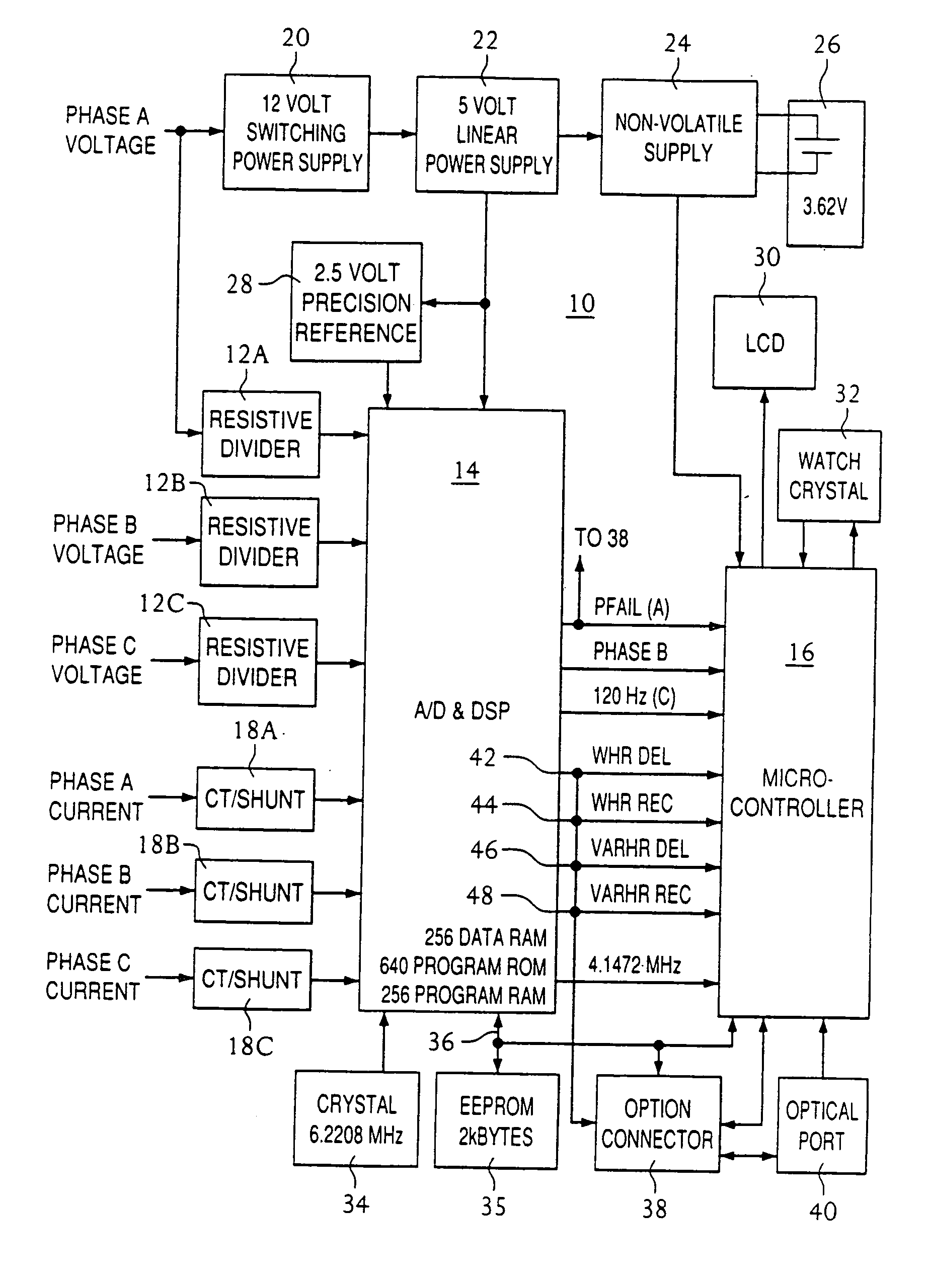
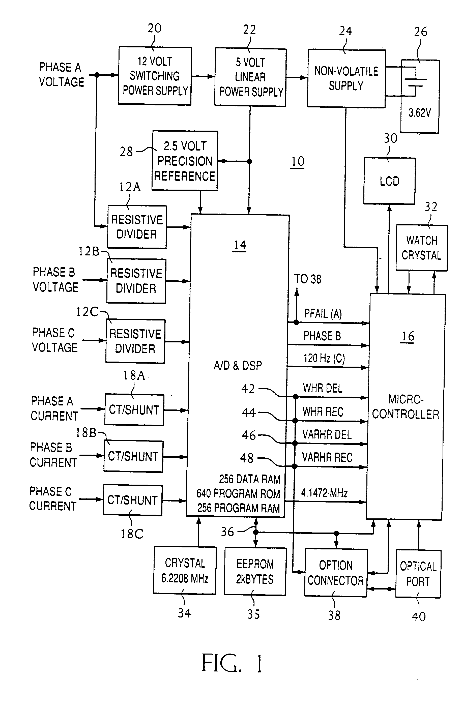
[0016] A new and novel meter for metering electrical energy is shown in FIG. 1 and generally designated 10. It is noted at the outset that this meter is constructed so that the future implementation of higher level metering functions can be supported.

[0017] Meter 10 is shown to include three resistive voltage divider networks 12A, 12B, 12C; a first processor—an ADC / DSP (analog-to-digital converter / digital signal processor) chip 14; a second processor—a microcontroller 16 which in the preferred embodiment is a Mitsubishi Model 50428 microcontroller; three current sensors 18A, 18B, 18C; a 12V switching power supply 20 that is capable of receiving inputs in the range of 96-528V; a 5V linear power supply 22; a non-volatile power supply 24 that switches to a battery 26 when 5V supply 22 is inoperative; a 2.5V precision voltage reference 28; a liquid crystal display (LCD) 30; a 32.768 kHz oscillator 32; a 6.2208 MHz oscillator 34 that provides timing signals to chip 14 and whose signal i...


PUM


Abstract

An electronic energy meter senses input voltage and current signals and processes the input voltage and current signals to generate measurements of multiple types of power. The meter comprises a processing system for selecting one of the multiple types of power and defining the same as the selected type of power. The processing system also generates a pulsed test signal representative of a magnitude of a measurement of the selected type of power for testing the operation of the meter. The meter further comprises a communications interface coupled to the processing system for transmitting the pulsed test signal from the meter and for receiving signals from sources external to the meter. Selection of one of the multiple types of power can be achieved by the meter receiving, via the communications interface and from a source external to the meter, a communications command identifying a selected one of the various types of power. The communications interface may comprise an optical communications port.

Description

RELATED APPLICATION DATA [0001] This application is a division of application Ser. No. 10 / 616,620, filed Jul. 10, 2003, which is a continuation of application Ser. No. 08 / 660,709, filed Jun. 6, 1996, which is a division of application Ser. No. 07 / 839,634, filed Feb. 21, 1992, now U.S. Pat. No. 5,537,029, the disclosures of all of which are herein incorporated by reference.FIELD OF INVENTION [0002] The present invention relates generally to the field of electric utility meters. More particularly, the present invention relates to both electronic watthour meters and meters utilized to meter real and reactive energy in both the forward and reverse directions. BACKGROUND OF THE INVENTION [0003] Techniques and devices for metering the various forms of electrical energy are well known. Meters, such as utility power meters, can be of two types, namely, electromechanical based meters whose output is generated by a rotating disk and electronic based meters whose output component is generated ...

Claims


Application Information

Patent Timeline
Patent Type & Authority Applications(United States)
IPC IPC(8): G01D4/00G01R7/00G01R11/32G01R13/02G01R21/133G01R22/00G01R22/10G01R31/28G01R35/04
CPCG01D4/00G01R21/133G01R22/00G01R22/10Y02B90/24Y02B90/248Y04S20/30Y04S20/52G01R35/04Y02B90/20
Inventor HEMMINGER, RODNEY C.MUNDAY, MARK L.
Owner ELSTER ELECTRICTY LLC
Learn More