Limited slip differential device suitable for downsizing

a limited slip differential and downsizing technology, applied in mechanical equipment, transportation and packaging, gearing, etc., can solve the problem of difficult downsizing of the outside shape of the aforementioned limited slip differential devi

Inactive Publication Date: 2005-12-01
TOYOTA JIDOSHA KK
View PDF4 Cites 15 Cited by
  • Summary
  • Abstract
  • Description
  • Claims
  • Application Information

AI Technical Summary

Benefits of technology

[0008] An object of the present invention is to provide a limited slip differential device which allows downsizing.
[0013] Since the limited slip differential device according to the present invention has a structure in which the carrier and the ring gear are sandwiched between the first and second sidewall portions of the ring gear, a thrust reaction force generated to perform a differential limitation function can be held without providing a housing to cover the ring gear from the outside. Therefore, an outside diameter of the device can be decreased.
[0014] Furthermore, with the thrust washer provided between the first sidewall portion and the sun gear, the thrust reaction force can be held more securely.
[0016] In particular, vehicle mountability can be increased by arranging the limited slip differential device according to the present invention in parallel with the auxiliary limited slip differential device along a direction intersecting with the concentric axis, that is, with a direction of transmission of a driving force.

Problems solved by technology

Therefore, while downsizing of a limited slip differential device is desired in terms of vehicle mountability, downsizing of an outside shape of the aforementioned limited slip differential device is difficult because casing material 39 for receiving the thrust force of internal gear 53 is provided outwardly in a radial direction of internal gear 53.

Method used


Image

  • Limited slip differential device suitable for downsizing
  • Limited slip differential device suitable for downsizing
  • Limited slip differential device suitable for downsizing

Examples


Embodiment Construction

[0026] An embodiment of the present invention will now be described referring to the drawings. In the embodiment described in the following, the same or corresponding portions are indicated with the same reference characters and descriptions thereof will not be repeated.

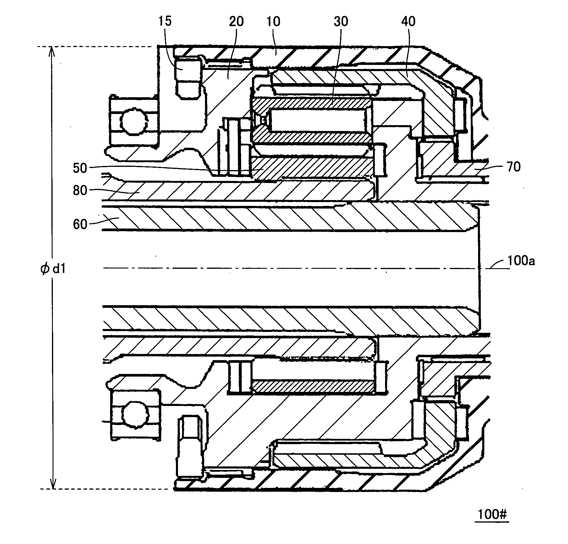
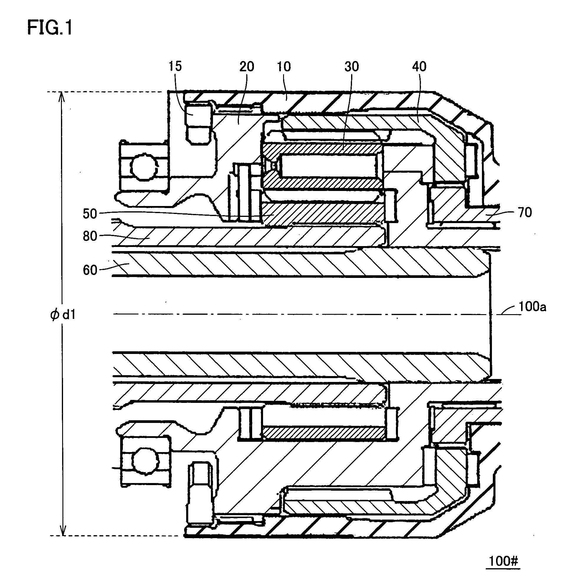
[0027] First, a structure of a limited slip differential device 100# shown as a comparative example is described using FIG. 1.

[0028] Referring to FIG. 1, limited slip differential device 100# includes a housing 10, a carrier 20, a pinion gear 30 held by carrier 20, and a sun gear 50 and a ring gear 40 engaging with pinion gear 30.

[0029] Carrier 20 is coupled to an input shaft 60 so as to rotate with input shaft 60 receiving a driving force transmitted from a transmission.

[0030] Though it is not shown in the drawing in detail, a plurality of pinion gears 30 are held in an internal space of carrier 20 along a circumferential direction of a concentric rotation axis 100a. Helical teeth are provided on a surface of pi...


PUM


Abstract

Helical teeth are provided on surfaces of a pinion gear, a ring gear and a sun gear, and ring gear is arranged on a concentric axis with sun gear in a relatively rotatable manner. The helical teeth of pinion gear engage with both helical teeth of sun gear and ring gear. Carrier is arranged on the concentric axis with sun gear in a rotatable manner relative to sun gear and ring gear, and supports pinion gear in a rotatable manner. With a structure of ring gear sandwiching carrier and ring gear with a first sidewall portion and a second sidewall portion provided to extend inwardly in a radial direction, a thrust reaction force generated to perform a differential limitation function can be held without providing a housing to cover ring gear from the outside. With this, downsizing of a limited slip differential device can be attained.

Description

[0001] This nonprovisional application is based on Japanese Patent Application No. 2004-159384 filed with the Japan Patent Office on May 28, 2004, the entire contents of which are hereby incorporated by reference. BACKGROUND OF THE INVENTION [0002] 1. Field of the Invention [0003] The present invention relates to a limited slip differential device and, more specifically, to a limited slip differential device used as, for example, a center differential (center diff) of a four-wheel drive vehicle. [0004] 2. Description of the Background Art [0005] A planetary gear torque-sensing LSD (Limited Slip Differential) structure is known as a limited slip differential device used as, for example, a center diff of a vehicle for distribution of a driving force (torque) between front and rear wheels and generation of a force for differential limitation (for example, a publication of Japanese Patent Laying-Open No. 2002-195381). [0006] The limited slip differential device disclosed in FIG. 1 of th...

Claims


Application Information

Patent Timeline
IPC IPC(8): B60K17/346F16H48/28F16H48/285F16H48/38
CPCF16H48/285B60K17/3465
Inventor YOSHIMURA, TAKAHIRO
Owner TOYOTA JIDOSHA KK
Why Eureka
Try Eureka