
Microfluidic system with integrated permeable membrane

a microfluidic system and permeable membrane technology, applied in the field of microfluidic devices and systems, can solve the problems of unfavorable contamination levels, difficult or expensive fabrication, carry-over artifacts,

Inactive Publication Date: 2005-12-01
CYTODISCOVERY
View PDF19 Cites 495 Cited by
  • Summary
  • Abstract
  • Description
  • Claims
  • Application Information

AI Technical Summary

Problems solved by technology

Adsorption and absorption of the above substances can cause undesirable levels of contamination, carry-over artifacts, depletion of compounds from solutions delivered to assay sites in biochemical and cell based assays, and background fluorescence or other signals due to absorption of fluorescent and non-fluorescent biological assays reporter groups in the PDMS.
This can cause significant problems if it is desired to measure the fluorescence intensity or lifetime of a fluorophore within a microfluidic channel and use the information in the determination of the result of a biological or biochemical assay.
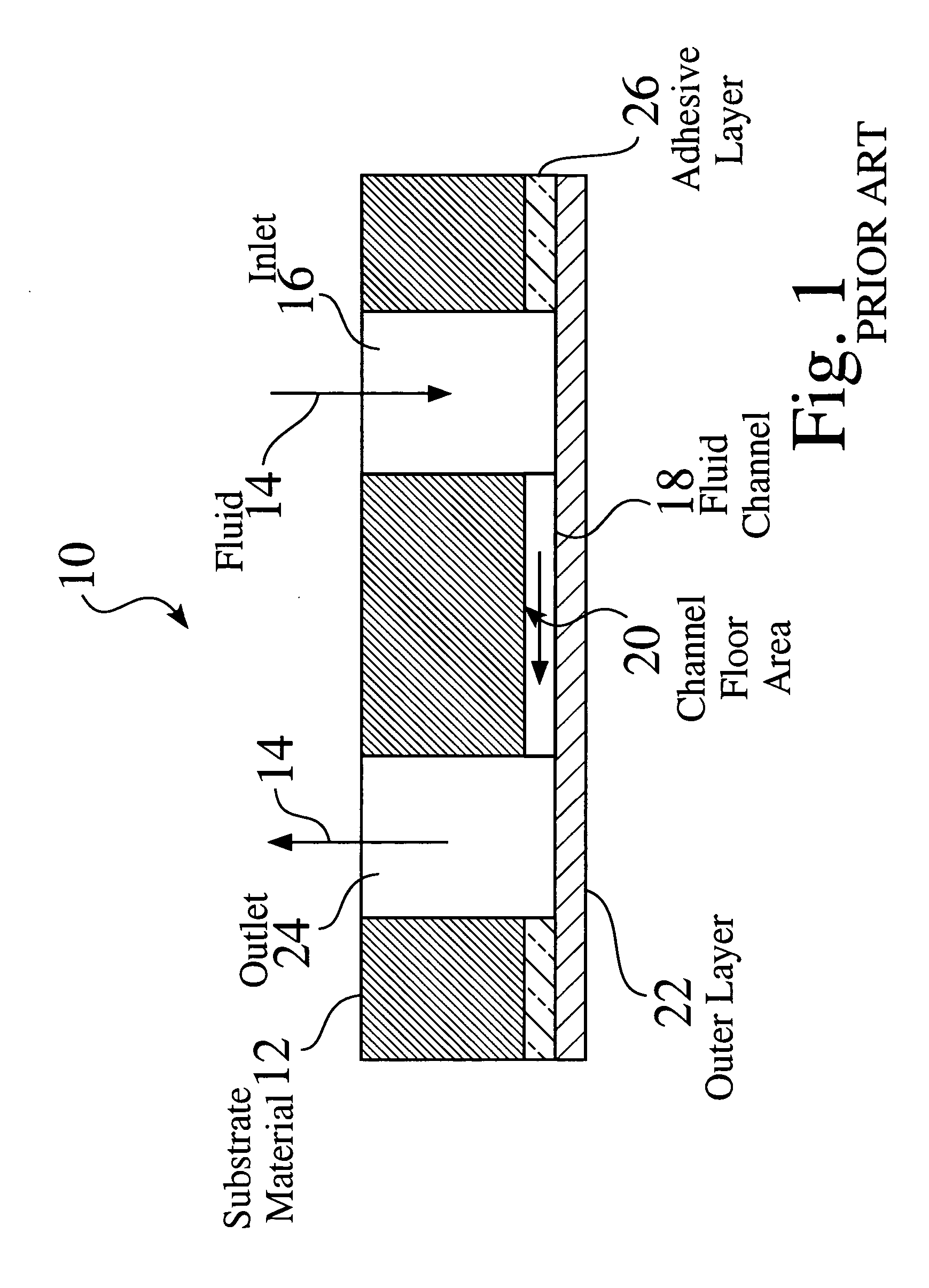
A limitation of this prior art embodiment is that it is difficult or expensive to fabricate, in practice, thin channels (<about 25 microns) and narrow channels (<about 100 microns) due to the inherent limitations of physical material removal such as physical material excision and laser cutting processes as well as the difficulties associated with alignment and lamination of structures with small feature sizes.
Plastic molding and stamping techniques can be employed to fabricate adhesive layer 26 but high tooling costs and long tool fabrication times can limit the utility of this method.
Bubbles formed in the channel during priming with fluid or in operation can not readily escape other than in the initial priming process.
Additionally, a dead-end channel can not be purged of gas and filled from one inlet port.
The net effect is that test compounds are absorbed into the PDMS in an unpredictable way.
This is highly undesirable for screening assays both since test compound may not be predictably delivered to its destination and there may be undesirable carry-over if the fluid is switched from one test compound to another.
Another problem with chip assembly 70, as taught by the prior art is that the large size of the gradient generator makes the device impractical to “scale-up” to provide large numbers of assays as is routinely required for drug screening assays, i.e., preferably to hundreds or even many thousands of assays per day.
Moreover, the prior art does not teach a method for doing a screening assay with a test compound but only a method for inducing chemotaxis in a gradient of chemoattractant formed in a channel with neurtophils attached therein.
Last, the device taught by the prior art provides only a one dimensional chemoattractant concentration gradients to be formed in the channel thus limiting the amount of information available to be obtained.
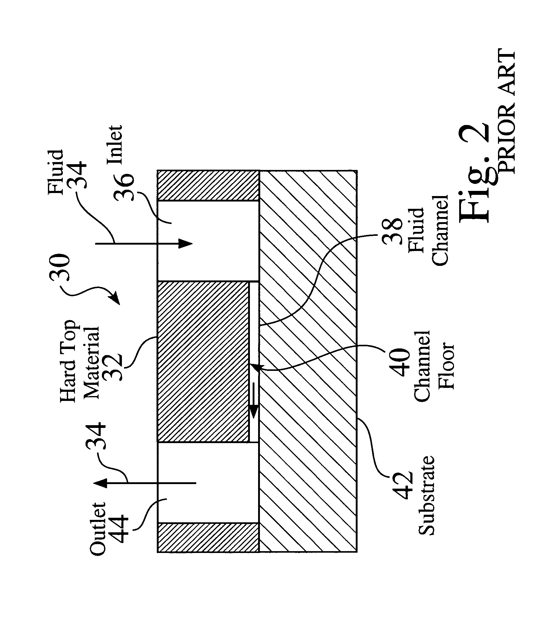
Unfortunately, the use of hard materials leads to sensitivity to leakage due to trapping of particulate matter.

Method used


Image

  • Microfluidic system with integrated permeable membrane
  • Microfluidic system with integrated permeable membrane
  • Microfluidic system with integrated permeable membrane

Examples


embodiment 340

[0153]FIG. 15 illustrates an embodiment 340 wherein the valve actuation access ports 342a and 344a are located on the side of chip opposite the exemplary fluid access port 346.

embodiment 350

[0154]FIG. 16 illustrates an embodiment 350 wherein the valve actuation access ports 342b and 344b are located on the same side of chip as the exemplary fluid access port 356.

[0155] In the embodiments shown in FIGS. 14-16, it is possible for the pressure distribution channels to cross over fluid channels without collapsing them when pressure is applied, i.e., activating a parasitic valve, since the area of the valve as designed is much larger than the cross over area of exemplary pressure distribution channel 326 and exemplary fluid channel 334. This means that whereas the force applied to a designated valve is sufficient to cause the valve to close; this is not the case for a cross over where the force is not sufficient to cause a parasitic valve to close. An important aspect of the design and implementation of practical and useful valves is that the membrane is deflectable with a reasonable applied pressure. Parameters which affect the deflection pressure are the valve area, chann...


PUM


Abstract

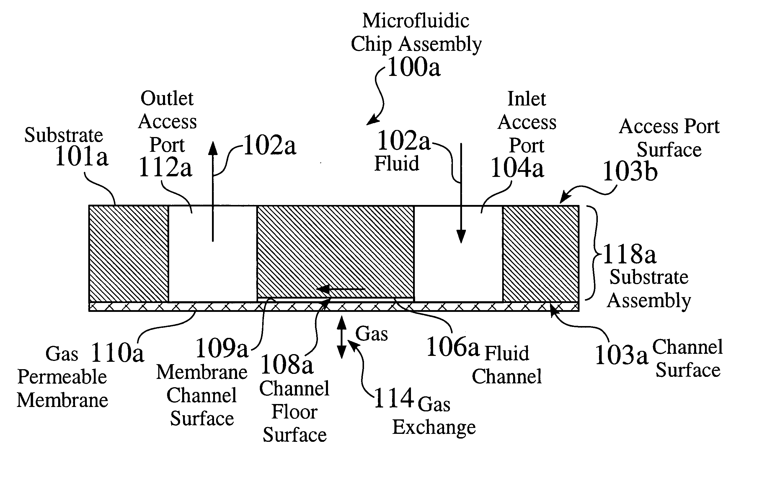
A microfluidic system for performing chemical reactions or biochemical, biological, or chemical assays utilizing a microfabricated device or “chip.” The system may include, among others, an integrated membrane fabricated from a chemically inert material whose permeability for gases, liquids, cells, and specific molecules, etc. can be selected for optimum results in a desired application.

Description

CROSS REFERENCES TO RELATED APPLICATIONS [0001] This application is a continuation-in-part of PCT Patent Application Serial No. PCT / U.S.2003 / 40107, filed Dec. 16, 2003, which in turn is partially based upon and claims the benefit under 35 U.S.C. § 119(e) of the following U.S. provisional patent applications: Ser. No. 60 / 462,957, filed Apr. 14, 2003; Ser. No. 60 / 434,286, filed Dec. 16, 2002; and Ser. No. 60 / 453,766, filed Mar. 10, 2003. This application also is partially based upon and claims the benefit under 35 U.S.C. § 119(e) of U.S. Provisional Patent Application Ser. No. 60 / 562,594, filed Apr. 14, 2004. These U.S. provisional and PCT patent applications each are incorporated herein by reference in their entirety for all purposes.FIELD OF THE INVENTION [0002] The present teachings relates generally to microfluidic devices and systems and methods for their use. More particularly, the present teachings relate to microfluidic devices and systems for performing chemical, biochemical,...

Claims


Application Information

Patent Timeline
IPC IPC(8): B01L3/00G01N21/00G01N21/05G01N21/25G01N21/77G01N21/78
CPCB01L3/5025G01N2021/0346B01L3/502707B01L3/502723B01L3/502738B01L3/502761B01L3/502776B01L2200/027B01L2200/0636B01L2200/0684B01L2300/0816B01L2300/0822B01L2300/0829B01L2300/0861B01L2300/0864B01L2300/0887B01L2300/10B01L2400/0406B01L2400/0487B01L2400/0655G01N21/05G01N21/253G01N21/6428G01N21/77G01N21/78G01N2021/6482G01N2021/7763G01N2021/7769B01L3/5027
Inventor MODLIN, DOUGLAS N.CHAZAN, DAVID
Owner CYTODISCOVERY
Learn More