
Image processing apparatus

Inactive Publication Date: 2005-12-01
CANON KK
View PDF9 Cites 12 Cited by
  • Summary
  • Abstract
  • Description
  • Claims
  • Application Information

AI Technical Summary

Benefits of technology

[0023] Another object of the invention is provide an apparatus which can easily convert the encoded moving image data into the encoded moving image data having the different frame rate.

Problems solved by technology

In such the conventional apparatus, there is a problem that the use of combination of the parameters increases complication of the stream to impose a load on the decoding process.
Therefore, sometimes the normal reproduction cannot be performed in a decoding apparatus or system in which MPEG is partially loaded.
However, as described above, when the recording is performed by the MPEG encoding of the video signal having 30 frames per second after the 2-3 pull-down, in the reproduction, it is difficult to re-convert the video signal having 30 frames per second into the video signal having 24 frames per second which has no redundancy before the pull-down.
Therefore, there are problems that it takes a very long time to perform the process and image quality is degraded by the re-encoding.

Method used


Image

  • Image processing apparatus
  • Image processing apparatus
  • Image processing apparatus

Examples


first embodiment

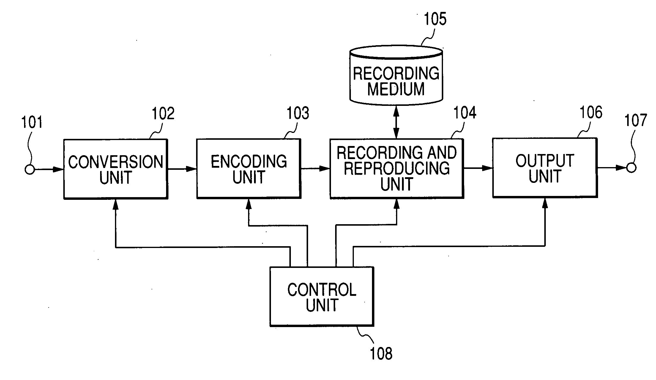
[0033]FIG. 1 shows a block diagram of a configuration of the image processing apparatus in a first embodiment. In FIG. 1, the reference numeral 101 denotes a video signal input terminal, the reference numeral 102 denotes a conversion unit, the reference numeral 103 denotes an encoding unit, the reference numeral 104 denotes a recording and reproducing unit which gets access to a recording medium 105 in order to read and write data, the reference numeral 105 denotes the writable recording medium such as a disk and a magnetic tape, the reference numeral 106 denotes an output unit which outputs a stream to an output terminal 107, the reference numeral 107 denotes the output terminal such as IEEE1394 and USB, and the reference numeral 108 denotes a control unit which controls each block.

[0034] The video signal having a frame rate of 24 frames per second is input from the video signal input terminal 101, and is supplied to the conversion unit 102. The conversion unit 102 inserts one fra...

second embodiment

[0053] Then, a second embodiment will be described. In the second embodiment, the image processing apparatus has the same configuration as for the first embodiment shown in FIG. 1.

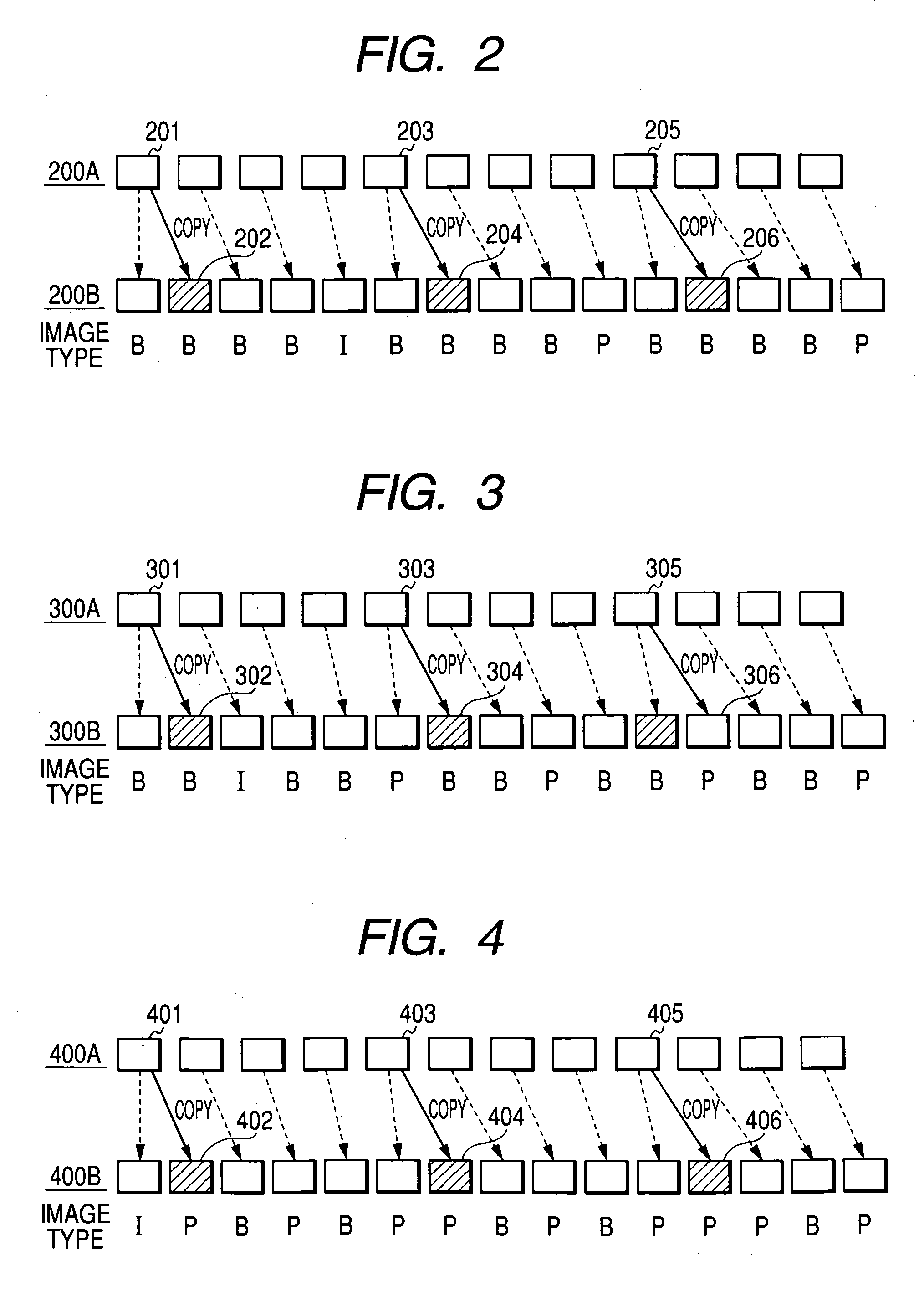
[0054] In MPEG, one GOP is constructed by the I picture of one frame and predetermined numbers of P frames and B frames, and the encoding process is performed in unit of GOP. At this point, a variable M indicating the number of frames from the I picture to the P picture or the number of frames between the P pictures is used as a variable expressing the structure of GOP. In the first embodiment, the distance between the I picture and the P picture and the distance between the P pictures are set at five frames, so that M=5. This is because the copy frame inserted when converting the four frames into five frames is securely encoded as the B picture.

[0055] However, in the case of the GOP configurations except for M=5, the first embodiment cannot support the GOP configurations. Therefore, in the second embodi...

third embodiment

[0066] Then, a third embodiment will be described. In the third embodiment, the image processing apparatus has the same configuration as for the first embodiment shown in FIG. 1.

[0067] In the first embodiment, the redundant frame which can be removed during the conversion of the stream having 30 frames per second into the stream having 24 frames per second is set at the B picture. In the third embodiment, the configuration in which the P picture is removed will be described.

[0068]FIG. 4 shows an example of the converting process performed by the conversion unit 102. A copy frame 402 of a frame 401 is inserted after the frame 401, a copy frame 404 of a frame 403 is inserted after the frame 403, and a copy frame 406 of a frame 405 is inserted after the frame 405. Therefore, the input data having four frames are converted into the data having five frames. The control unit 108 gives the direction of the timing at which the copy frames are inserted.

[0069] The conversion unit 102 suppl...


PUM


Abstract

A signal processing apparatus includes a conversion unit, an encoding unit, and a control unit. The conversion unit converts first moving image data having a first frame rate into second moving image data having a second frame rate by inserting a new frame into the first moving image data having the first frame rate at predetermined timing. The encoding unit encodes the second moving image data having the second frame rate by selectively using intra-frame encoding and inter-frame prediction encoding. The encoding unit classifies each frame of the second moving image data as a first frame type which is not referred to in the inter-frame prediction encoding and a second frame type which is referred to in the inter-frame prediction encoding, and the encoding unit encodes the second moving image data according to the classification result. The control unit controls the encoding unit such that the frame inserted by the conversion unit among the second moving image data is encoded by classifying the inserted frame as a particular frame type.

Description

BACKGROUND OF THE INVENTION [0001] 1. Field of the Invention [0002] The present invention relates to a signal processing apparatus and method, particularly relates to the signal processing apparatus and method which are preferably used to process moving image stream data in which compression encoding is performed. [0003] 2. Related Background Art [0004] Recently, with progress of a digital signal processing technology, a large amount of digital information such as a moving image, a still image, and sound can be encoded at high efficiency to record the encoded information in a small magnetic medium or a small optical medium or to transmit the encoded information through a communication medium. Further, such the technology is applied to development of an image pickup apparatus which can easily take high-quality video image to immediately output the video image to an information medium. [0005] Particularly, an MPEG encoding technology is used in the recent moving image encoding. In the...

Claims


Application Information

Patent Timeline
IPC IPC(8): H04N5/91H04N19/50H04N7/12H04N19/114H04N19/503H04N19/577H04N19/70
CPCH04N7/0112H04N19/587H04N19/132H04N19/46
Inventor NOZAWA, SHINGO
Owner CANON KK
Learn More