Bifocal multiorder diffractive lenses for vision correction
- Summary
- Abstract
- Description
- Claims
- Application Information
AI Technical Summary
Problems solved by technology
Method used
Image
Examples
example 1
[0045] Consider an ophthalmic lens prescription requiring a correction of −7 diopters for distance vision, with a +2 diopter add power for near vision. Thus, the two powers (denoted by φ) of the lens are
φdistance=−7D
φnear=−5D (=−7+2)
The radial locations (rj) of the diffractive zones from the center of the lens are given by rj=2j p λ0ϕ0
where j is the zone number, p is the MOD number, λ0 is the design wavelength, and φ0 is the desired optical power of the lens. [See Eq. (1) of the above-incorporated U.S. Patent, with φ0=1 / F0.]
[0046] In this example, λ0=555 nm (peak of photopic response). If p=11, the zone radii within a clear aperture diameter of 12 mm for the distance power are
Distance power (−7 D)ZONE NUMBER (j)ZONE RADIUS (rj)11.32071421.86777232.28754442.64142852.95320663.23507673.49428183.73554493.962142104.176465114.380313124.575088134.761902144.941660155.115104165.282856175.445444185.603315195.756859205.906413
[0047] Similarly, for the near power, the zone radii are...
example 2
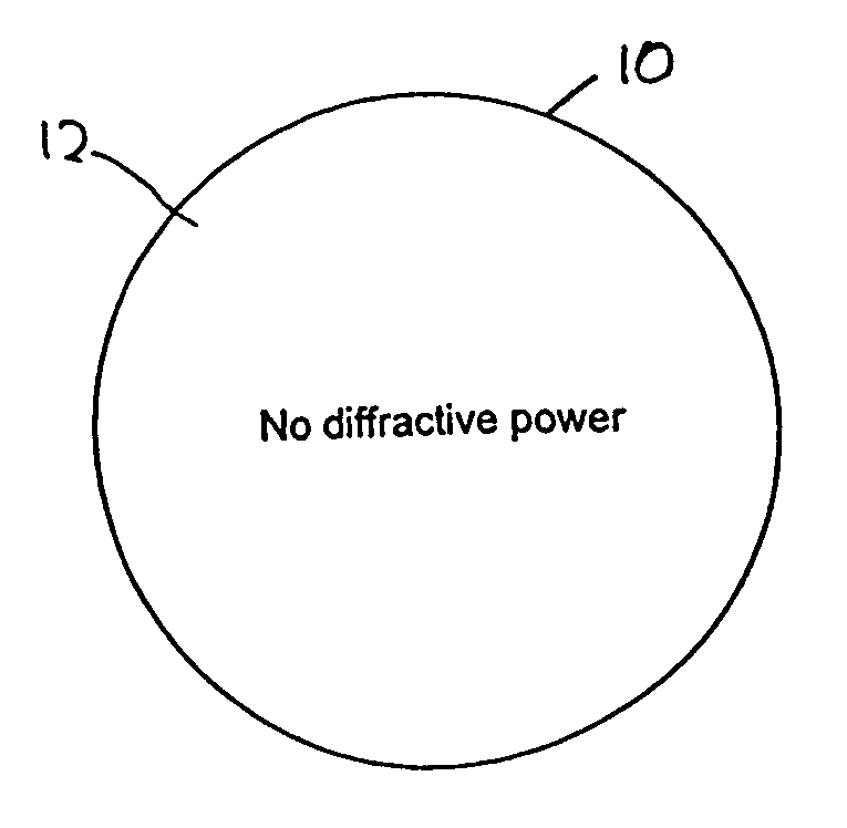
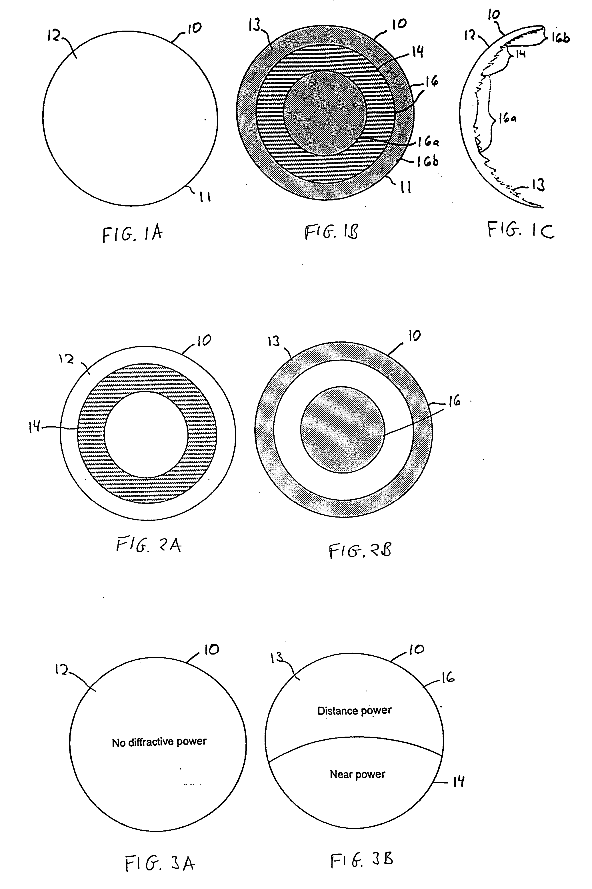
[0048] To construct the bifocal MOD lens along the same surface, as shown in FIGS. 1A-1C, all the diffractive power is contained in circular / annular regions of one surface of the lens. The distance power is contained in regions 16a and 16b of FIG. 1B, while the near power is contained in region 14. We choose the radius of region 16a to be 2 mm, the outer radius of region 14 to be 4 mm and the outer radius of region 16b to be 6 mm. Then, the zone locations for the bifocal lens are the radii of the individual power components that lie within these region boundaries. There are no diffractive zones on the other side of the lens.
Zone locations for bifocal MOD lensZONE NUMBER (j)ZONE RADIUS (rj)11.320714distance21.867772distance32.209977near42.706658near53.125380near63.494281near73.827793near84.176465distance94.380313distance104.575088distance114.761902distance124.941660distance135.115104distance145.282856distance155.445444distance165.603315distance175.756859distance185.906413distance
N...
example 3
[0049] Another option is to place the near power on one surface of the lens and the distance power on the other surface, as in the lens of FIGS. 2A and 2B. In this embodiment, the zone locations are
First SurfaceZONE NUMBER (j)ZONE RADIUS (rj)12.209977near22.706658near33.125380near43.494281near53.827793near
[0050] No diffractive zones for radius less than 2.0 mm or radius greater than 4.0 mm.
Second SurfaceZONE NUMBER (j)ZONE RADIUS (rj)11.320714distance21.867772distance34.176465distance44.380313distance54.575088distance64.761902distance74.941660distance85.115104distance95.282856distance105.445444distance115.603315distance125.756859distance135.906413distance
[0051] No diffractive zones for radius greater than 2.0 mm and less than 4.0 mm.
[0052] For all of the above examples, the height of the zones is given by h=p λ0nlens(λ0)-nmedium(λ0)
[See Eq. (4) of above-incorporated U.S. Patent.]
[0053] If the lens is in air, then nmedium(λ0)=1.0. Also, if the lens is constructed of a mate...
PUM
 Abstract
Description
Claims
Application Information
 - R&D
- Intellectual Property
- Life Sciences
- Materials
- Tech Scout
- Unparalleled Data Quality
- Higher Quality Content
- 60% Fewer Hallucinations
Browse by: Latest US Patents, China's latest patents, Technical Efficacy Thesaurus, Application Domain, Technology Topic, Popular Technical Reports.
© 2025 PatSnap. All rights reserved.Legal|Privacy policy|Modern Slavery Act Transparency Statement|Sitemap|About US| Contact US: help@patsnap.com


