
Method and apparatus for isolating against mechanical dynamics

Inactive Publication Date: 2005-12-01
BAKER HUGHES INC
View PDF17 Cites 14 Cited by
  • Summary
  • Abstract
  • Description
  • Claims
  • Application Information

AI Technical Summary

Benefits of technology

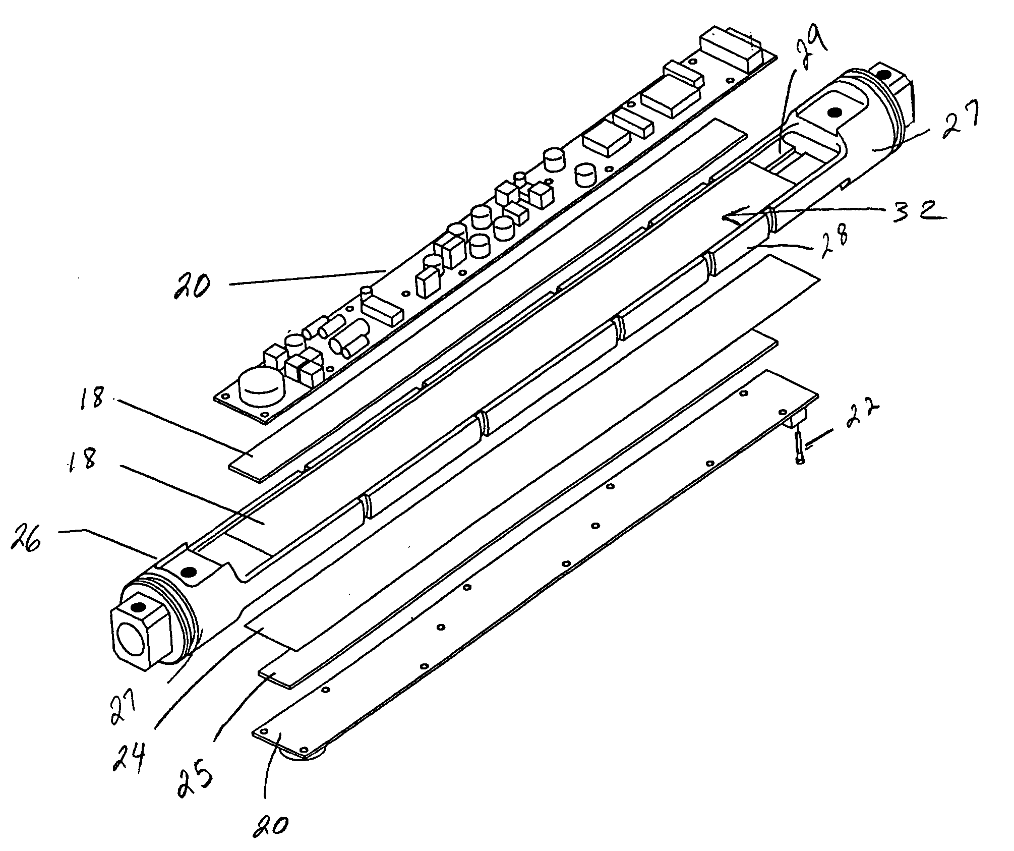
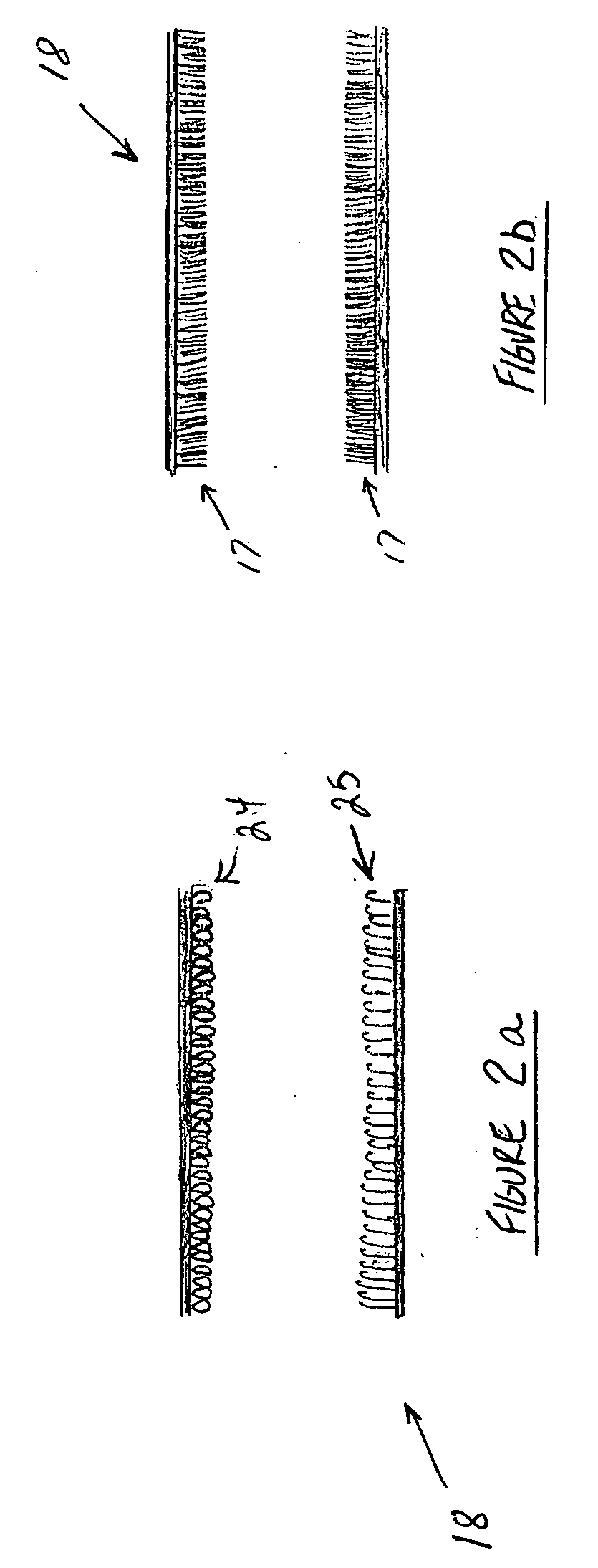
[0034] The present invention described herein, therefore, is well adapted to carry out the objects and attain the ends and advantages mentioned, as well as others inherent therein. While a presently preferred embodiment of the invention has been given for purposes of disclosure, numerous changes exist in the details of procedures for accomplishing the desired results. For example, in addition to the hooks and loops and multiplicity of opposing fingers above described, the damping strip 18 can also contain a series of hooks and hooks, loops and loops, fingers and hooks, or fingers and loops. These variations and other similar modifications will readily suggest themselves to those skilled in the art, and are intended to be encompassed within the spirit of the present invention disclosed herein and the scope of the appended claims.

Problems solved by technology

In many of the applications where electrical processing devices are implemented, they are subjected to some type of shock and vibration.
As such these devices are subject to failure or diminished functional capacity when they experience some types of vibration and / or shock.
Downhole tools also often experience high shock and vibration conditions either during use within a wellbore, or during handling after they have been assembled and prior to use within a wellbore.
Often times the shock or vibration can damage the downhole components thereby rendering the component inoperable or ineffective.
Further, the shock and vibration during use can cause the downhole component to provide erroneous data, this is especially so when the downhole component is a sensor monitoring data downhole for later analysis.
However these static suspension systems can often amplify the effects of shock induced vibration instead of minimizing the effect.

Method used


Image

  • Method and apparatus for isolating against mechanical dynamics
  • Method and apparatus for isolating against mechanical dynamics
  • Method and apparatus for isolating against mechanical dynamics

Examples


Embodiment Construction

[0021] With reference to the drawing herein, an embodiment of the present invention is illustrated in a side view in FIG. 1. A device 12 is shown releaseably secured to a surface 10 by a pair of damping strips 18. The device 12 can be any device susceptible to being damaged or adversely affected by mechanical dynamic forces, such as shock, vibration and shock or vibration. Examples of such devices include without limitation electrical components, such as electrical circuit boards, avionics, data recording devices, electrical receivers and transmitters, and sensors. The surface 10 therefore can represent the structure or base on which the device 12 is typically secured. Examples of possible foundations 10 include electrical component mounting boards found in computers, bulkheads / shelves in aircraft, mounting surfaces for downhole components within downhole tools, and other securing surfaces for mechanically dynamic sensitive devices. Each damping strip 18 is comprised of a damping ma...


PUM


Abstract

An apparatus and method to isolate downhole components within a downhole tool from shock and vibration typically experienced during handling and use of the downhole tool. The apparatus and method include a series of interlocking hooks and loops that are bondable to the downhole component and dampingly secure the downhole component within the downhole tool. The material comprising the interlocking hooks and loops is a high temperature material whose performance is not affected by high temperatures.

Description

BACKGROUND OF THE INVENTION [0001] 1. Field of the Invention [0002] The invention relates generally to the field of isolating devices from mechanical dynamics. More specifically, the present invention relates to a method and apparatus to provide damping for components sensitive to shock and vibration. [0003] 2. Description of Related Art [0004] The recent past has seen a ubiquitous implementation of electrical processing devices and equipment containing data processing components such as printed circuit boards, integrated circuits, resistors, capacitors and the like. These devices can now be found in automobiles, motorcycles, aircraft, and ships. They are also in use in other devices such as computers, microprocessors, electrical controllers, and sensors. In many of the applications where electrical processing devices are implemented, they are subjected to some type of shock and vibration. While the electrical processing devices do function basically as conduits or switches for elec...

Claims


Application Information

Patent Timeline
IPC IPC(8): F16F7/08F16F15/02F16M13/00
CPCF16F7/08F16F2222/04F16F15/02E21B47/01
Inventor THIGPEN, EARL B.BURROUGHS, EDWARD GLENNBOCHAIN, MARK M.
Owner BAKER HUGHES INC
Learn More