
Flexible board electrical connector

a flexible board and electrical connector technology, applied in the direction of coupling contact members, coupling device connections, electrical apparatus, etc., can solve the problem of unfavorable release of actuators from the housing, and achieve the effect of preventing the disengagement of actuators and high reliability

Inactive Publication Date: 2005-11-24
HON HAI PRECISION IND CO LTD
View PDF5 Cites 35 Cited by
  • Summary
  • Abstract
  • Description
  • Claims
  • Application Information

AI Technical Summary

Benefits of technology

[0007] An object of the present invention is to provide an electrical connector which is capable of preventing disengagement of an actuator with high reliability.
[0008] Another object of the present invention is to provide a flexible board electrical connector which is capable of suppressing the risk of disengagement of an actuator even if a flexible flat cable or flexible printed circuit board connected to the connector is subjected to pull force.
[0009] In order to achieve the above object, a flexible board electrical connector according to the present invention for a flexible circuit includes an insulative housing defining a circuit-insertion slot in one face thereof and a pair of actuator holes in opposite sides thereof, a number of terminals mounted to the housing and spaced along the slot for engaging conductors spaced along the flexible circuit, an actuator having a shaft pivotally located in the actuator holes for movement between an open position allowing insertion of the flexible circuit into the slot and a closed position biasing the circuit and its conductors against the contact portions of the terminals, and a pair of positioning members formed on the shaft to prevent the shaft from falling out of the actuator holes.

Problems solved by technology

In this event, the actuator will undesiredly be released from the housing.

Method used


Image

  • Flexible board electrical connector
  • Flexible board electrical connector
  • Flexible board electrical connector

Examples


Embodiment Construction

[0014] The present invention will be discussed hereafter in detail in terms of the preferred embodiment of the present invention with reference to the accompanying drawings. In the following description, numerous specific details are set for the in order to provided a thorough understanding of the present invention. It will be obvious, however, to those skilled in the art that the present invention may be practiced without these specific detail. In other instances, well-known structures are not shown in detail in order to avoid unnecessary obscurity of the present invention

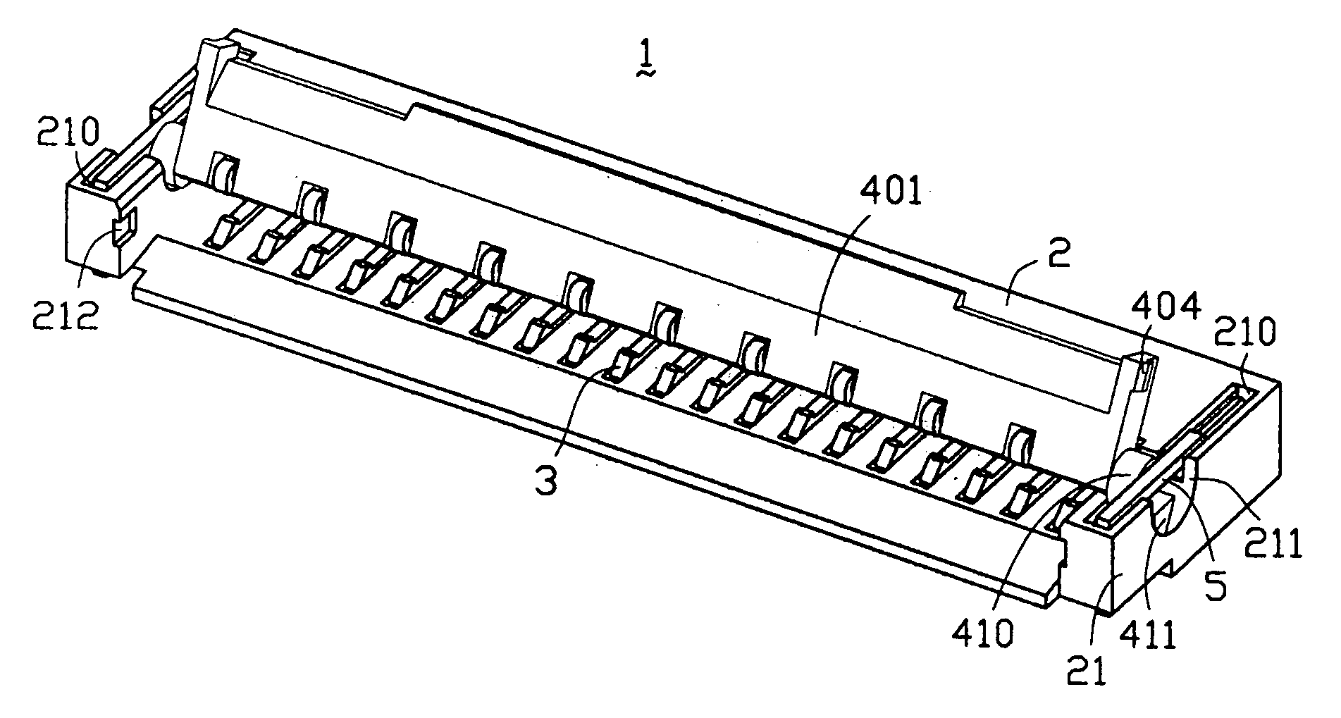
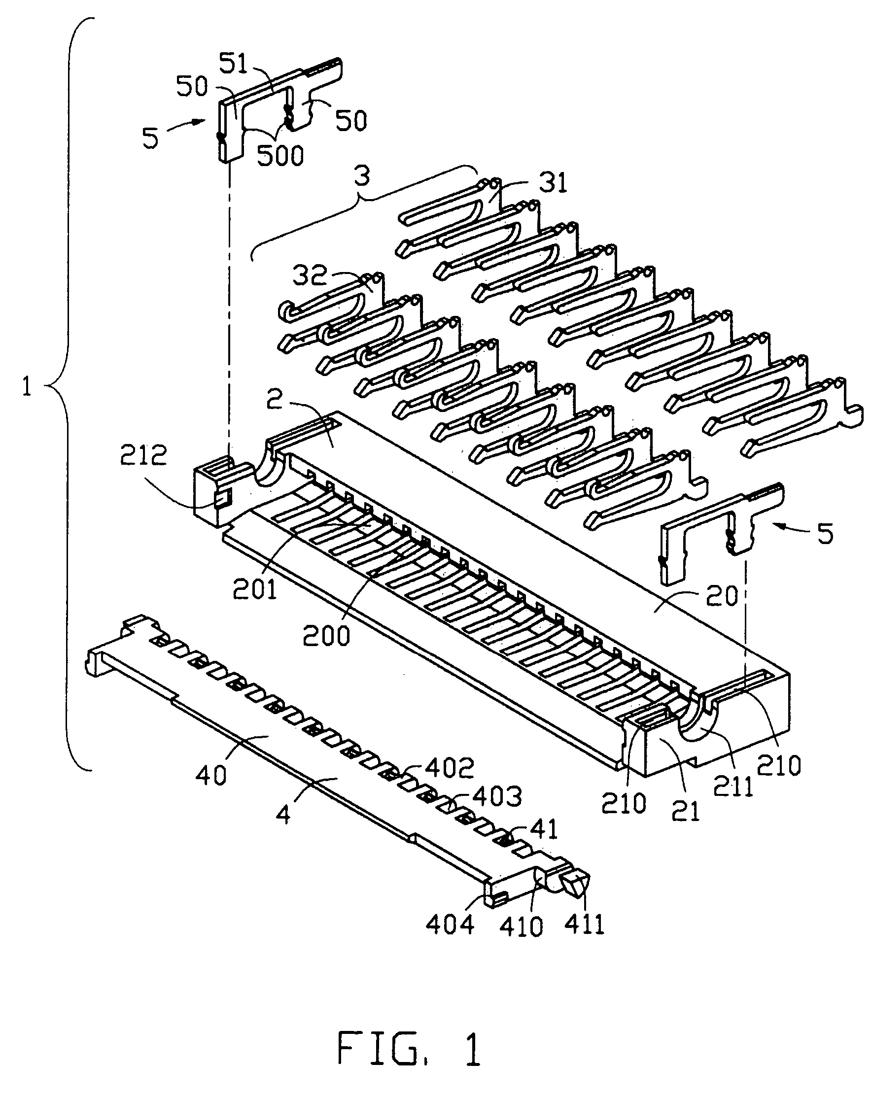
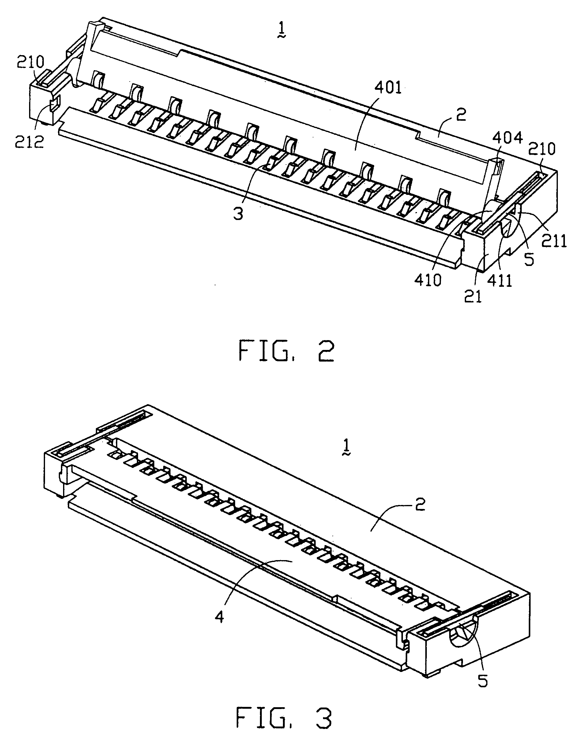
[0015] Referring to FIGS. 1-3, a flexible board electrical connector 1 in accordance with the present invention is adapted for connecting a flexible flat cable (FFC, not shown) or flexible printed circuit board (FPC, not shown) to a motherboard (not shown). The electrical connector includes an elongate insulative housing 2, a plurality of conductive terminals 3, an actuator 4 pivotally mounted on the housing 2 fo...


PUM


Abstract

An electrical connector (1) for a flexible circuit includes an insulative housing (2) defining a circuit-insertion slot (201) in one face thereof and a pair of actuator holes (211) in opposite sides thereof, a number of terminals (3) mounted to the housing and spaced along the slot for engaging conductors spaced along the flexible circuit, and an actuator (4) having a shaft (41) pivotally located in the actuator holes for movement between an open position allowing insertion of the flexible circuit into the slot and a closed position biasing the circuit and its conductors against the contact portions of the terminals, and a pair of positioning members (5) formed on the shaft to prevent the shaft from falling out of the actuator holes.

Description

BACKGROUND OF THE INVENTION [0001] 1. Field of the Invention [0002] The present invention relates to electrical connectors and more particularly, to an electrical connector for flexible flat cables or flexible printed circuit boards. [0003] 2. Description of Related Art [0004] Typical electrical connectors for flexible flat cables (FFC) or flexible printed circuit boards (FPC) comprise an insulating or dielectric housing having an insertion aperture and a plurality of terminals disposed within the housing in side-by-side relationship with a predetermined pitch. The terminals have contact portions which extend into the insertion aperture in such a way that they can contact conductive areas of the FFC or FPC. The housing also often comprises a pivoting actuator (pressure clamp) which can be moved from an “open” state in which the FFC or FPC can be inserted into the insertion aperture, into a “closed” state in which the FFC or FPC and the connections thereof are pressed against the con...

Claims


Application Information

Patent Timeline
IPC IPC(8): H01R12/08H01R12/16H01R12/24H01R13/24
CPCH01R12/79H01R13/24H01R12/88
Inventor LU, YAO PANG
Owner HON HAI PRECISION IND CO LTD
Learn More