
Divergent flap for a gas turbine engine

a gas turbine engine and divergent flap technology, applied in the direction of machines/engines, sustainable transportation, mechanical equipment, etc., can solve the problems of difficult attachment of cmc material components to metal components, the design of planes to avoid radar detection has become an important issue, and the operation of typical gas turbine engines in an extremely harsh environment characterized by very high temperatures and vibrations, etc., to achieve the effect of minimizing the detection of planes

Active Publication Date: 2005-11-24
RTX CORP
View PDF9 Cites 6 Cited by
  • Summary
  • Abstract
  • Description
  • Claims
  • Application Information

AI Technical Summary

Benefits of technology

"The present invention is about a new design for a divergent flap assembly in a gas turbine engine. It includes a hotsheet, a backbone structure, and a plow portion. The plow portion is made of CMC material and is attached to the backbone structure to bridge the gap between the hotsheet and an external flap. The backbone structure has openings that allow relative movement between it and the hotsheet, which helps to minimize offset between the hotsheet and the plow portion when the backbone structure thermally expands. The plow portion is fastened to the backbone structure by a plurality of fasteners that are arranged to minimize thermal stresses. The flap assembly also includes an aft support extending axially from the backbone structure toward the trailing edge of the flap assembly to minimize deflection of the hotsheet. The technical effects of this design include improved engine efficiency, reduced emissions, and reduced noise."

Problems solved by technology

A typical gas turbine engine operates in an extremely harsh environment characterized by very high temperatures and vibrations.
In military operations, design of planes to avoid detection by radar has become an important issue.
However, it is difficult to attach the CMC material components to metal components.
One obstacle to attaching the CMC material to the metal is different thermal expansions of the materials.
In general, it is difficult to attach or join different materials in a gas turbine engine due to different thermal expansion properties.

Method used


Image

  • Divergent flap for a gas turbine engine
  • Divergent flap for a gas turbine engine
  • Divergent flap for a gas turbine engine

Examples


Embodiment Construction

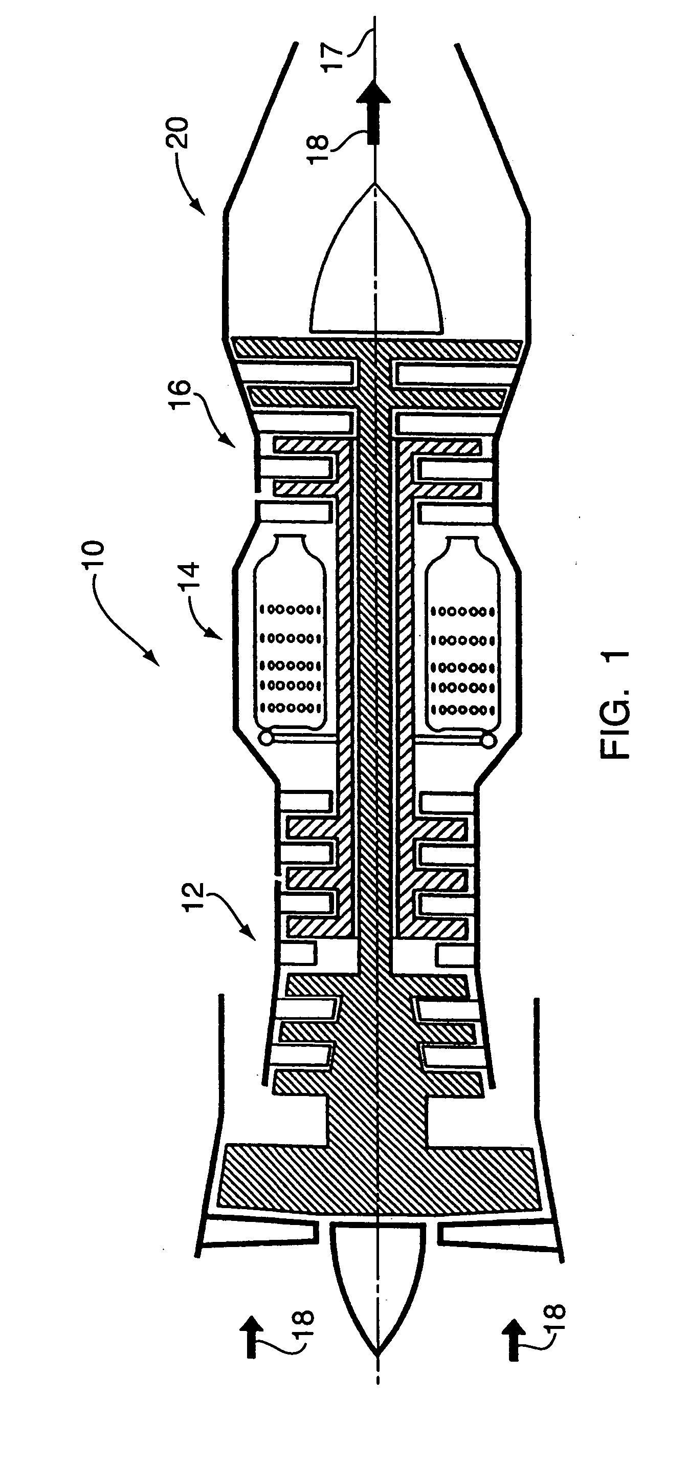
[0025] Referring to FIG. 1, a gas turbine engine 10 includes a compressor 12, a combustor 14, and a turbine 16 centered around a central axis 17. Air 18 flows axially through the engine 10. As is well known in the art, air 18 is compressed in the compressor 12. Subsequently, the compressor air is mixed with fuel and burned in the combustor 14. The hot gases expand generating thrust to propel the engine 10 and to drive the turbine 16, which in turn drives the compressor 12. The exhaust gases from the turbine 16 exit through the exhaust nozzle 20.

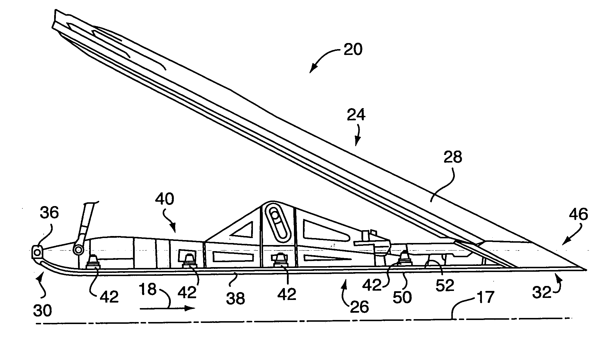
[0026] Referring to FIG. 2, the exhaust nozzle 20 includes a plurality of external flaps 24 arranged circumferentially about the axis 17 and a plurality of divergent flaps 26 disposed radially inward from the external flaps. Each external flap 24 includes an external flap surface 28 having a particular geometry. Each divergent flap 26 includes a fore portion 30 and an aft portion 32. The fore portion 30 includes a hinge assembly 36 for secur...


PUM

PropertyMeasurementUnit
thermal stressesaaaaaaaaaa
structureaaaaaaaaaa
temperaturesaaaaaaaaaa

Abstract

A divergent flap assembly of a gas turbine engine includes a hotsheet, a backbone structure for supporting the hotsheet, and a plow portion secured to the backbone structure to bridge a gap between the hotsheet and an external flap. The plow portion is fabricated from CMC material and has external geometry to complement and substantially continue geometry of the external flap to minimize plane detection. The plow portion is attached to the backbone structure such that when the backbone structure thermally expands, the plow portion is shifted to minimize an offset between a trailing edge of the hotsheet and the plow portion. The plow portion is fastened to the backbone structure by a plurality of fasteners, which are arranged to minimize thermal stresses.

Description

[0001] The invention was made under a U.S. Government contract and the Government has rights herein.BACKGROUND OF THE INVENTION [0002] 1. Technical Field [0003] The present invention relates to gas turbine engines and, more particularly, to a divergent flap therefor. [0004] 2. Background Art [0005] A typical gas turbine engine operates in an extremely harsh environment characterized by very high temperatures and vibrations. A conventional gas turbine engine includes a compressor for compressing entering air, a combustor for mixing and burning the compressed gases that emerge from the compressor with fuel, a turbine for expanding the hot gases to generate thrust to propel the engine, and an exhaust nozzle for allowing hot gases to exit the engine. Thus, the exhaust nozzle must accommodate extremely hot gases exiting the engine. [0006] In military operations, design of planes to avoid detection by radar has become an important issue. The ability of the plane to remain undetected, also...

Claims


Application Information

Patent Timeline
Patent Type & Authority Applications(United States)
IPC IPC(8): F02C7/00F02K1/12F02K1/54F02K1/58F02K1/80F02K1/82
CPCF02K1/12F02K1/54F02K1/805F05D2300/603Y02T50/672Y02T50/675F05D2300/21F02K1/822Y02T50/60
Inventor ARBONA, JAIME A.
Owner RTX CORP
Learn More