
Wall element

a wall element and module technology, applied in the field of modules large wall elements, can solve the problems of inflexible configuration of wall elements, unsuitable use in practice, unfavorable use as partitions or exhibition walls, etc., and achieve the effect of easy cleaning

Inactive Publication Date: 2005-11-24
MIRROR IMAGE INC
View PDF33 Cites 16 Cited by
  • Summary
  • Abstract
  • Description
  • Claims
  • Application Information

AI Technical Summary

Benefits of technology

[0009] Many advantages are obtained in this way: not only is there thus produced a highly decorative and at the same time functional and practical partition wall or interior design object with a high-quality surface which is easy to clean (because it is made of glass), but at the same time the combination of decorative design for the wall panel with a cut-out for the flat screen provides the possibility of flexible visual moving image media with the option of configuring the area around the screen cut-out as a decorative design by means of logos, typefaces, large photo displays or other such designs which are effective in the company or exhibition sector.
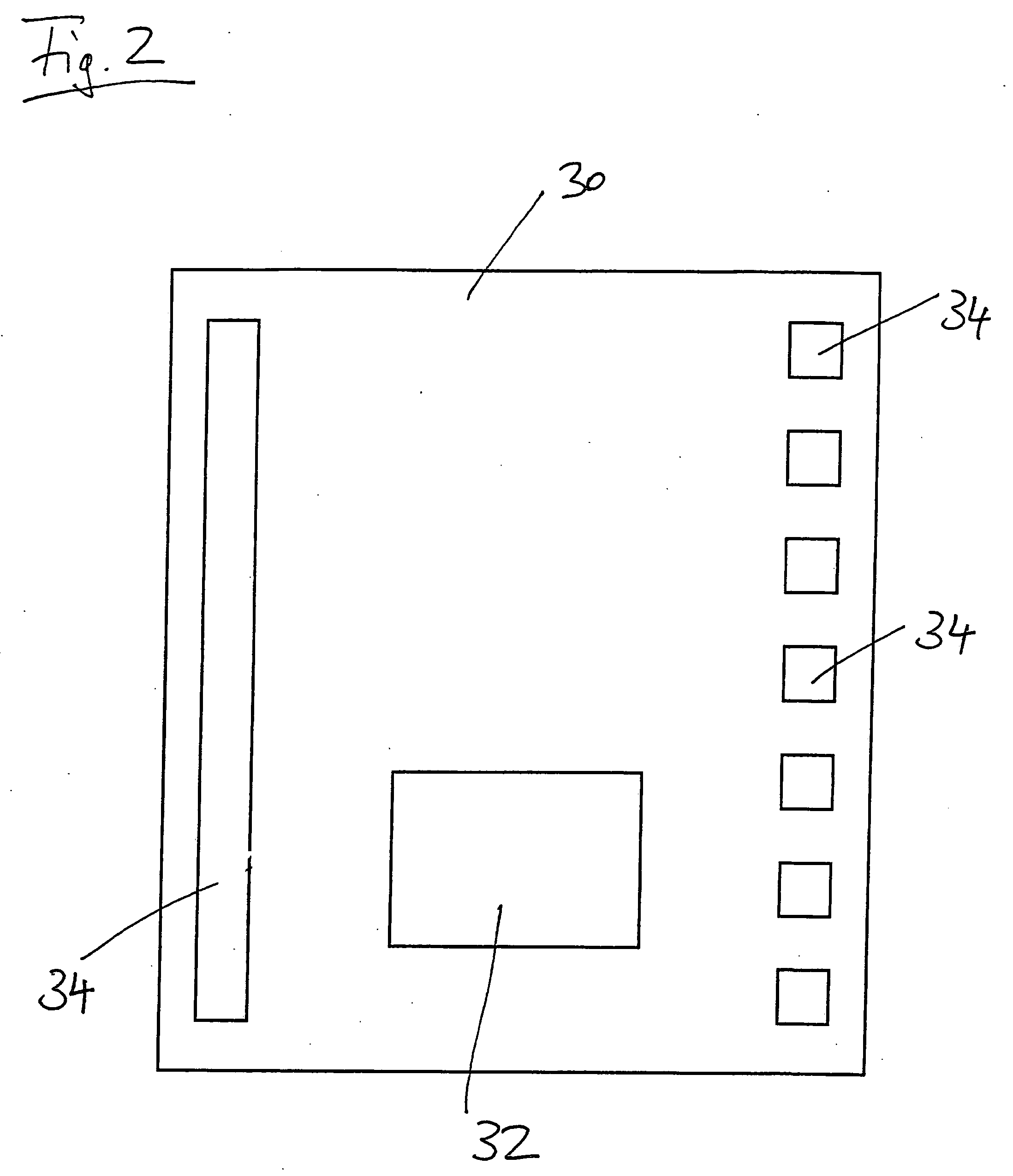
[0011] The modular encapsulation of the flat screen in the associated housing according to the invention also has an effect with regard to simple handling and easy replacement, wherein the housing may contain all the necessary power supply, control and possibly receiving and / or image generation units, and the provision of a suitable bulk memory for the electronic image display is also conceivable, this being integrated in the housing (for example in the form of a DVD drive). It is also conceivable to allow wireless transmission of image data by suitably incorporating transmitter and receiver units, these also being provided in the encapsulated flat screen.
[0013] Such an arrangement then expands the usability of the wall element by virtue of an additional lighting functionality, wherein, in one development, it is also possible for suitable light programmes, light colour variants or the like to be suitably preselected or set (perhaps by remote-control). By using light sources, such as LEDs or fluorescent tubes for example, which make it possible to illuminate within a colour spectrum (RGB or the like), the wall element can also serve as a mood lighting means in addition to the aforementioned lighting function. It is possible for the user to set individual colour tones of the wall element. In this case, a remote control of the flat screen, which can be used according to one development, performs two functions at the same time: on the one hand the remote control can be used to control the functionality of the screen unit, and on the other hand it is possible to control the lighting means by virtue of this remote control, e.g. setting colour patterns, switching the light sources on and off, etc. Compared to conventional systems, the system is thus very convenient for the user to operate, since just one remote control is required. The remote control may be designed in the customary transmission methods—infrared, radio or the like.
[0024] As a result, the present invention provides a wall element which can advantageously be used as a room divider, partition wall, decorative element, wall or bathroom mirror, sales display, exhibition wall or the like, and combines flexible display possibilities using modern electronic media with a high-quality surface which is easy to clean.

Problems solved by technology

However, such known wall elements have the disadvantage firstly that they are inflexible in terms of their configuration; typically, by (manually) applying the design, the optically effective configuration is permanently fixed and can then be changed only with difficulty.
Particularly for audiovisual presentations, such wall elements are not suitable in practice.
Although a use as a projection wall for video projectors or the like would be possible, such a use is nevertheless unfavourable for use as a partition or exhibition wall, since an observer would stand in the beam path between the projector and the wall.
Another problem associated with such known wall elements is the problematic cleaning thereof; this is because known wall elements typically have surfaces made of paper, plastic or the like which, besides being of limited quality, in the long term can be kept clean only with difficulty.
Such a technology, which would be used for example in the health sector, is nevertheless only suitable to a limited extent as a wall element for interior design.

Method used


Image

  • Wall element
  • Wall element
  • Wall element

Examples


Embodiment Construction

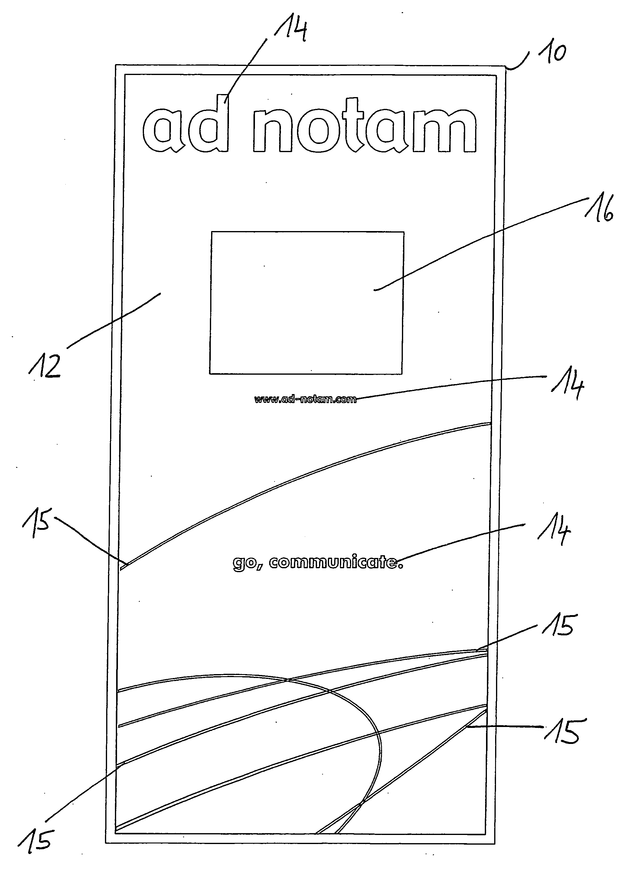
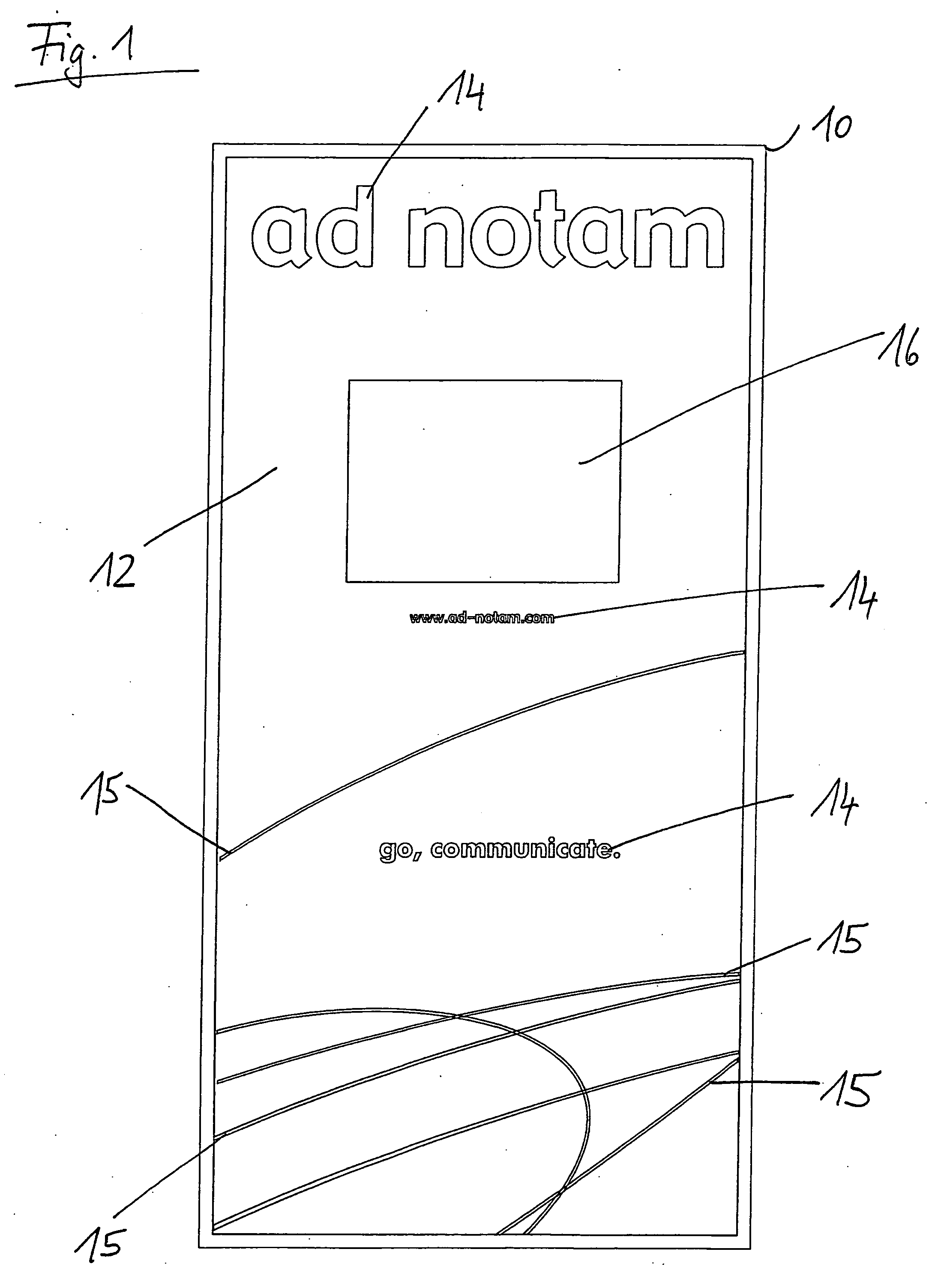
[0034]FIG. 1 shows a modular large wall element as a room divider according to a first preferred embodiment of the present invention. A metal frame 10 which is approximately 2 m high surrounds a glass panel 12 which is treated on its rear and is provided on its rear with a decorative colour by being printed over its entire area, wherein at the same time further design features 15 and letters 14 are formed for advertising purposes within the wall element by changing the colour tone or by partial mirroring.

[0035] The glass panel 12 patterned in this way has, as shown, a cut-out 16 which is dimensioned to receive a 30-inch TFT colour screen, wherein the cut-out 16 is formed as an area of the glass panel 10 which is left free in the colour design 12, 14, 15.

[0036] Placed behind this cut-out 16 is a flat screen which is accommodated in a special screen housing additionally comprising suitable power supply and control electronics, said flat screen being known from the prior art and bein...


PUM


Abstract

A wall panel has a glass outer face which in turn is provided with a decorative design, for example by painting, mirroring, partial mirroring, coating, printing or else placing an inlay or the like behind it. In addition, this wall panel is designed to cooperate with a flat screen in such a way that the decorative design forms a cut-out adapted to the flat screen, through which cut-out the image display can then be viewed on the user side.

Description

CROSS REFERENCE TO RELATED APPLICATION [0001] The instant application is a continuation-in-part of application Ser. No. 09 / 883,729 filed Jun. 18, 2001.BACKGROUND OF THE INVENTION [0002] The present invention relates to a modular large wall element for interior design, wherein the wall element is suitable for displaying information at the same time. [0003] Such devices are generally known in the form of partition or exhibition walls and also for flexible advertising purposes and comprise as the essential component a large wall panel, the outer face of which on the user side is configured decoratively in the intended manner, for example by applying designs in the form of logos, pictures, text or the like. [0004] However, such known wall elements have the disadvantage firstly that they are inflexible in terms of their configuration; typically, by (manually) applying the design, the optically effective configuration is permanently fixed and can then be changed only with difficulty. Part...

Claims


Application Information

Patent Timeline
Patent Type & Authority Applications(United States)
IPC IPC(8): G09F13/12G09F15/00
CPCG09F15/00G09F13/12Y10S40/90
Inventor ROTTCHER, OLIVER
Owner MIRROR IMAGE INC
Learn More