Screw tip and molding system apparatus
- Summary
- Abstract
- Description
- Claims
- Application Information
AI Technical Summary
Benefits of technology
Problems solved by technology
Method used
Image
Examples
Embodiment Construction
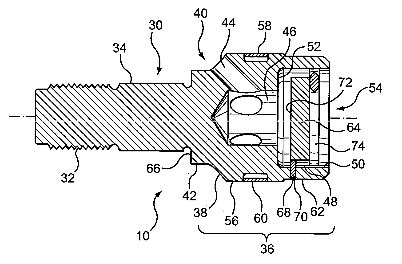
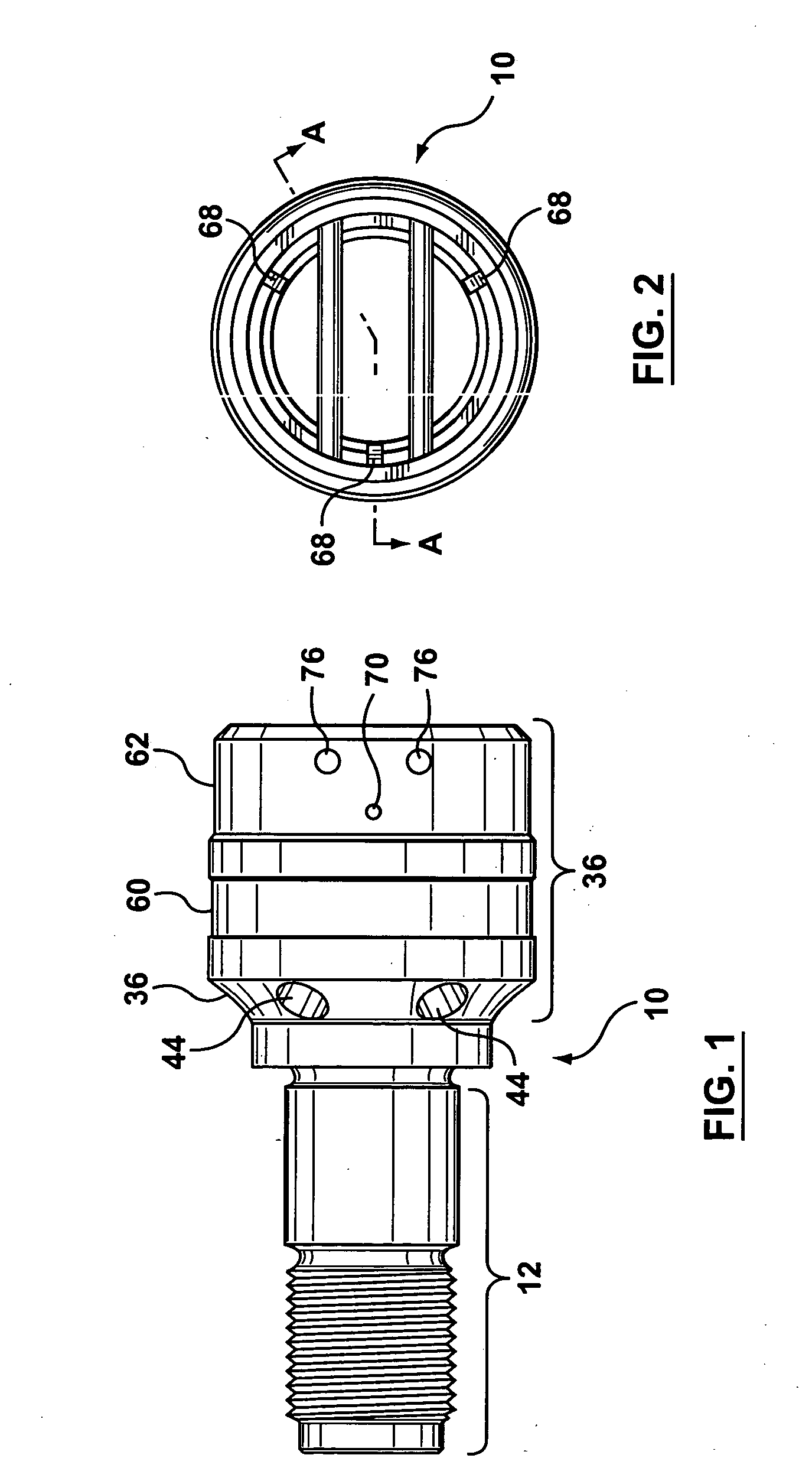
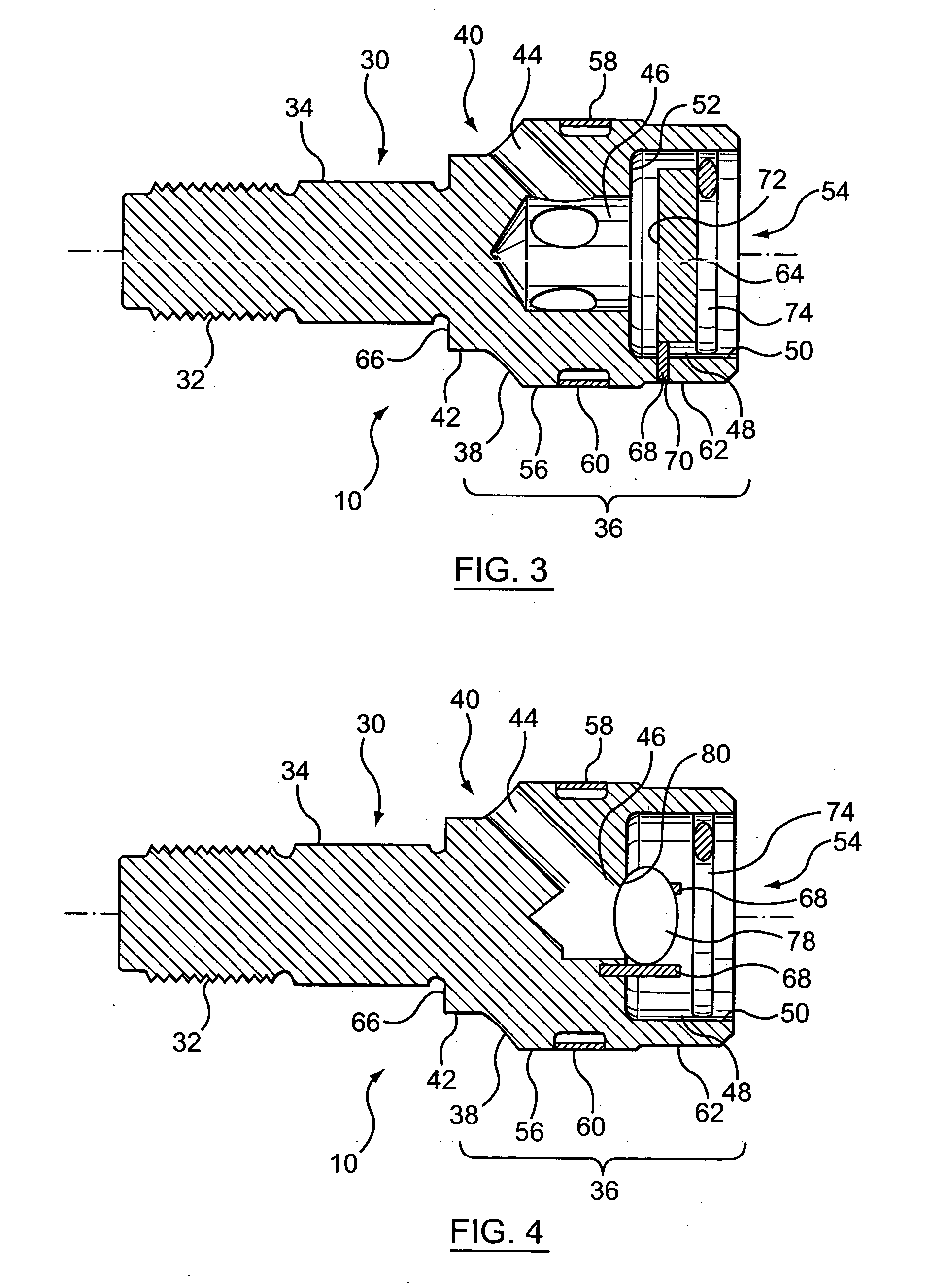
[0029] The present invention is described in accordance with an embodiment as illustrated with reference to FIGS. 1 and 2. A screw tip is illustrated generally at 10. The screw tip 10 includes a connection 12 section and a screw tip head 36 section. The connection 12 is for mounting and retaining the screw tip 10 with a screw (not shown). The screw tip head 36 houses the entry port 44 (or entry ports), central accumulator chamber 46, and check valve chamber 48 (see FIG. 3). The screw tip head 36 also houses a check valve 64 upon assembly.
[0030] The connection 12 and the screw tip head 36 of the invention are further described with reference to the cross sectional view illustrated in FIG. 3 which is taken along the line A-A of FIG. 2. The connection 12 has a substantially cylindrical body. The connection 12 has an engagement member 32, for example threads formed about a diameter of a cylindrical end. The engagement member 32 cooperates with complimentary threads in a cylindrical bor...
PUM
| Property | Measurement | Unit |
|---|---|---|
| Flow rate | aaaaa | aaaaa |
| Diameter | aaaaa | aaaaa |
| Circumference | aaaaa | aaaaa |
Abstract
Description
Claims
Application Information
 - R&D
- Intellectual Property
- Life Sciences
- Materials
- Tech Scout
- Unparalleled Data Quality
- Higher Quality Content
- 60% Fewer Hallucinations
Browse by: Latest US Patents, China's latest patents, Technical Efficacy Thesaurus, Application Domain, Technology Topic, Popular Technical Reports.
© 2025 PatSnap. All rights reserved.Legal|Privacy policy|Modern Slavery Act Transparency Statement|Sitemap|About US| Contact US: help@patsnap.com


