Flow meter device

a flow meter and flow direction technology, applied in the direction of mass flow measurement devices, measurement devices, instruments, etc., can solve the problems of distorting flow measurement, two flow meters influencing each other, etc., and achieve reliable operation and clear reduction of flow direction.

Active Publication Date: 2005-11-17
SIEMENS AG +1
View PDF8 Cites 20 Cited by
  • Summary
  • Abstract
  • Description
  • Claims
  • Application Information

AI Technical Summary

Benefits of technology

[0009] Because of the different eigenfrequencies, the effects of crosstalk are reduced. The different eigenfrequencies make it possible to keep the mutual influence of the two flow meters small enough such that there is no, or only a tolerable level of, interference with the measurement result.
[0024] Each flow meter preferably has an electronic control unit, such that the electronic control unit of the one flow meter monitors the electronic control unit of the other flow meter. The two control units can very well be structurally combined, e.g., on a common printed circuit board. However, the printed circuit board is divided into two sections, which are functionally completely separate, such that each section controls one flow meter. Furthermore, the two sections monitor each other by means of a monitoring circuit. If one section fails, the other section will take over the control and measurement. This has the advantage of ensuring a reliable operation even in differential flow measurements, which have to meet high standards.

Problems solved by technology

However, when two identical flow meters are used in the same housing, problems may arise by the two flow meters influencing each other.
Under unfavorable circumstances, however, these vibrations are also transmitted through the common housing from one flow meter to the other.
If both flow meters vibrate at the same frequency, this transmission causes significant interference and can distort the flow measurement results.

Method used


Image

  • Flow meter device
  • Flow meter device
  • Flow meter device

Examples


Embodiment Construction

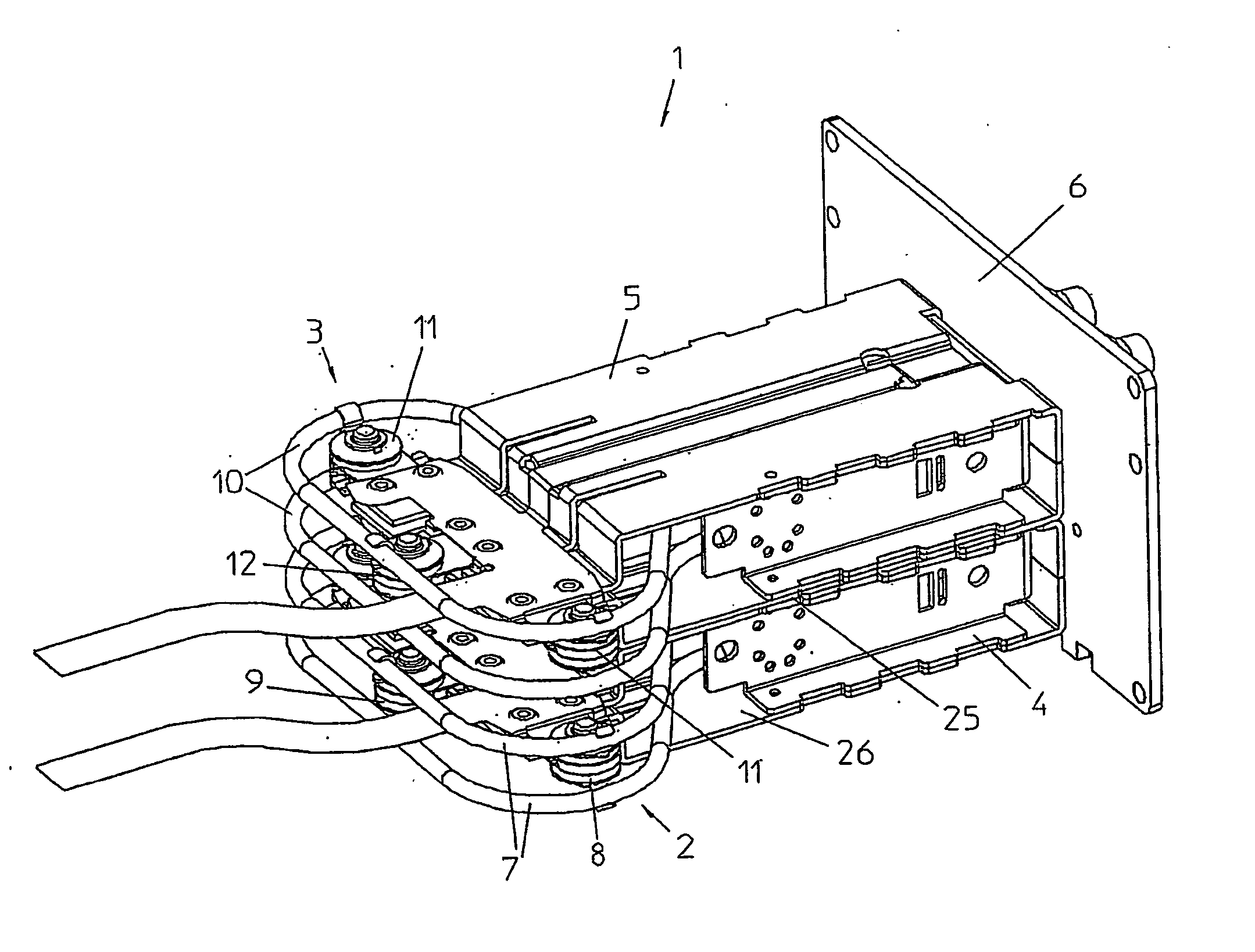
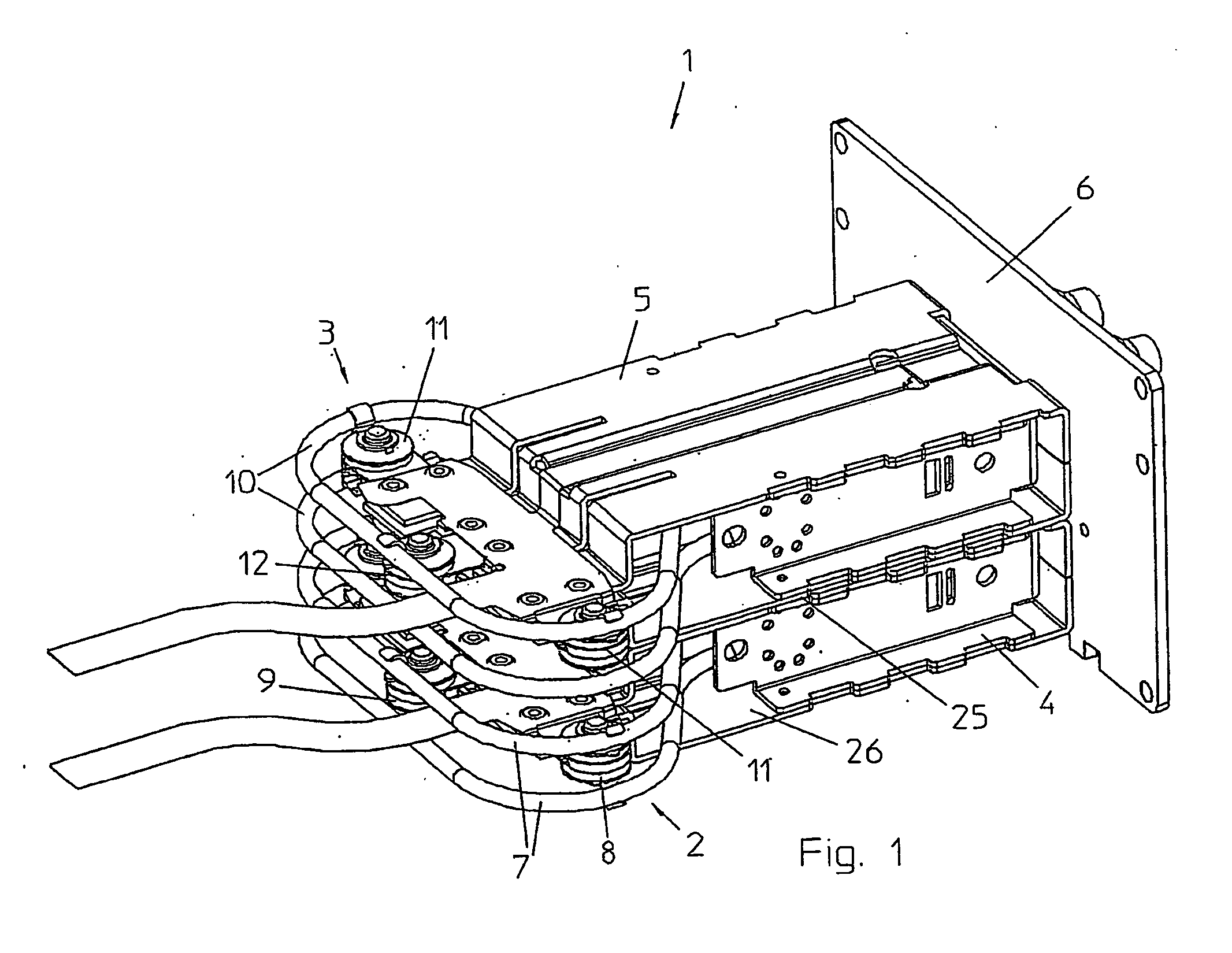
[0033] A flow meter device 1 depicted in FIG. 1 has two individual flow meters 2, 3, the chassis 4, 5 of which are mounted to a common front plate 6.

[0034] The flow meter 2 has a measuring tube 7, which is run in two loops. Sensors 8 and a driver 9 are disposed between the two loops. The flow meter 3 likewise has a measuring tube 10, which is run in two loops. Two sensors 11 and a driver 12 are located between the loops of the measuring tube 10.

[0035] The measuring tubes 7, 10 can be formed by parallel loops, that is to say, by two separate measuring tubes through which the fluid flows. It is also possible, however, to design the measuring tubes 7, 10 as continuous tubes as disclosed in WO 92 / 19940 A1.

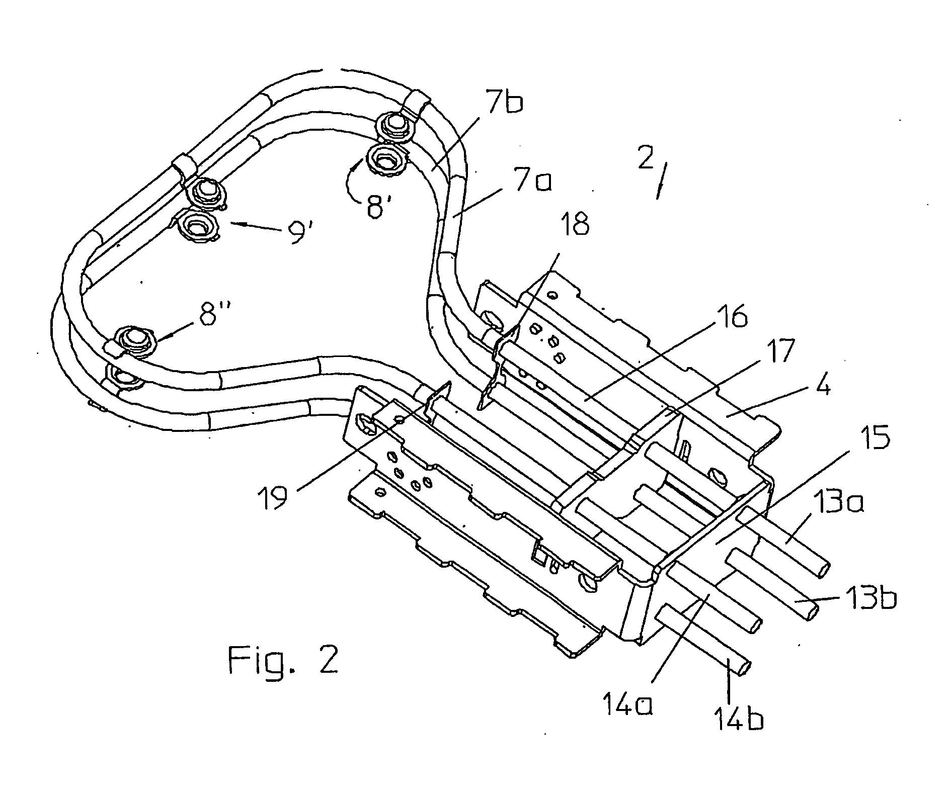
[0036]FIG. 2 shows an individual flow meter 2 in detail. The two measuring tube loops 7a, 7b are mounted on the chassis 4. The measuring tube 7a has an inlet 13a and an outlet 14a. The measuring tube 7b has an inlet 13b and an outlet 14b. The inlets and outlets 13a, 13b and 14a, 14b...


PUM


Abstract

A device having a first flow meter (2) and a second flow meter (3). The first and the second flow meters work according to a Coriolis principle. The first flow meter includes a first measuring tube (7). The second flow meter includes a second measuring tube (10). The first flow meter and the second flow meter are disposed in a common housing (4,5,6). The first flow meter and the second flow meters have different eigenfrequencies because of a first vibration-influencing device (18) attached to the first flow meter and a second vibration-influencing device (19) attached to the second flow meter.

Description

[0001] This is a Continuation of International Application PCT / DK2003 / 000534, with an international filing date of Aug. 12, 2003, which was published under PCT Article 21(2) in German, and the disclosure of which is incorporated into this application by reference.FIELD AND BACKGROUND OF THE INVENTION [0002] The invention relates to a flow meter device having a first flow meter, which works according to the Coriolis principles and is provided with a first measuring tube, and a second flow meter, which works according to the Coriolis principle and is provided with a second measuring tube. [0003] A flow meter device of this type is known from W. Kiehl, “Difference measurement using Coriolis mass flowmeters,” Flow Meas. Instrum., Vol. 2, April 1991, pp. 135 to 138. The use of two Coriolis flow meters is advantageous, for example, whenever the difference between two mass flows is to be determined. Determining this difference is useful if one wants to get information about a leak, for exa...

Claims


Application Information

Patent Timeline
IPC IPC(8): G01F1/84
CPCG01F1/8409G01F1/8477G01F1/8413
Inventor ANDRESEN, RIKKE VESTERBAEKJENSEN, STEEN SKYTTEMOELLER, HANS CHRISTIAN
Owner SIEMENS AG
Why Eureka
Try Eureka