
Method and apparatus for optimizing forging processes

Active Publication Date: 2005-11-10
SPECIALITY MINERALS (MICHIGAN) INC
View PDF8 Cites 11 Cited by
  • Summary
  • Abstract
  • Description
  • Claims
  • Application Information

AI Technical Summary

Benefits of technology

[0001] The use of open die forging to form and / or draw a metallic workpiece between upper and lower dies of a forging press is known, particularly with respect to forging operations of large size workpieces (e.g., for power generation machinery, crank shafts). One important aspect with respect to the quality of a forged product, is a uniform and thorough forging of the core of a workpiece in order to eliminate cavities and other inclusions in the workpiece that impair quality. To achieve a uniform consolidation of the center line, the center line being the direction in which the workpiece is moved forward and backward wherein the center of mass of the workpiece is considered the center line of a workpiece being forged. One process known as “cogging” is used to convert coarse-grained, cast ingot into fine-grained, wrought billet or in other words break down the coarse cast structure and consolidate internal defects in the work piece. In many forging shops, because of various constraints imposed by a large-scale forging operation of red-hot workpieces, forging processes are controlled by a human operator. In such processes, the operator controls center line consolidation by visual inspection to determine consolidation areas of the last forging pass, which appear as bright structures at the side of the workpiece. From experience, the operator then estimates the placement of the next cogging blows or “setup points” to improve centerline consolidation.

Problems solved by technology

Operator-related variations in process control and also variations of the achieved consolidation quality can result, however, which can lead to a high rejection rate in terms of quality management and economy.
These defects typically require additional forging and / or discarding of the workpiece that can result in the loss of work time, material, and / or energy costs.

Method used


Image

  • Method and apparatus for optimizing forging processes
  • Method and apparatus for optimizing forging processes
  • Method and apparatus for optimizing forging processes

Examples


Embodiment Construction

[0014] The invention is best understood by reference to the accompanying drawings in which like reference numbers refer to like parts. It is emphasized that, according to common practice, the various dimensions of the component parts of the apparatus as shown in the drawings are not to scale and have been enlarged for clarity. Also, the directional designations “left” or “right” are not to be construed as limited to any specific orientation but, rather, are for reference purposes as they pertain to the views as shown in the drawing figures.

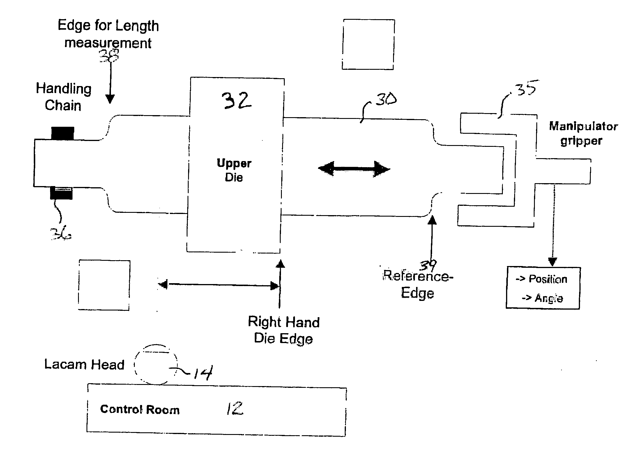
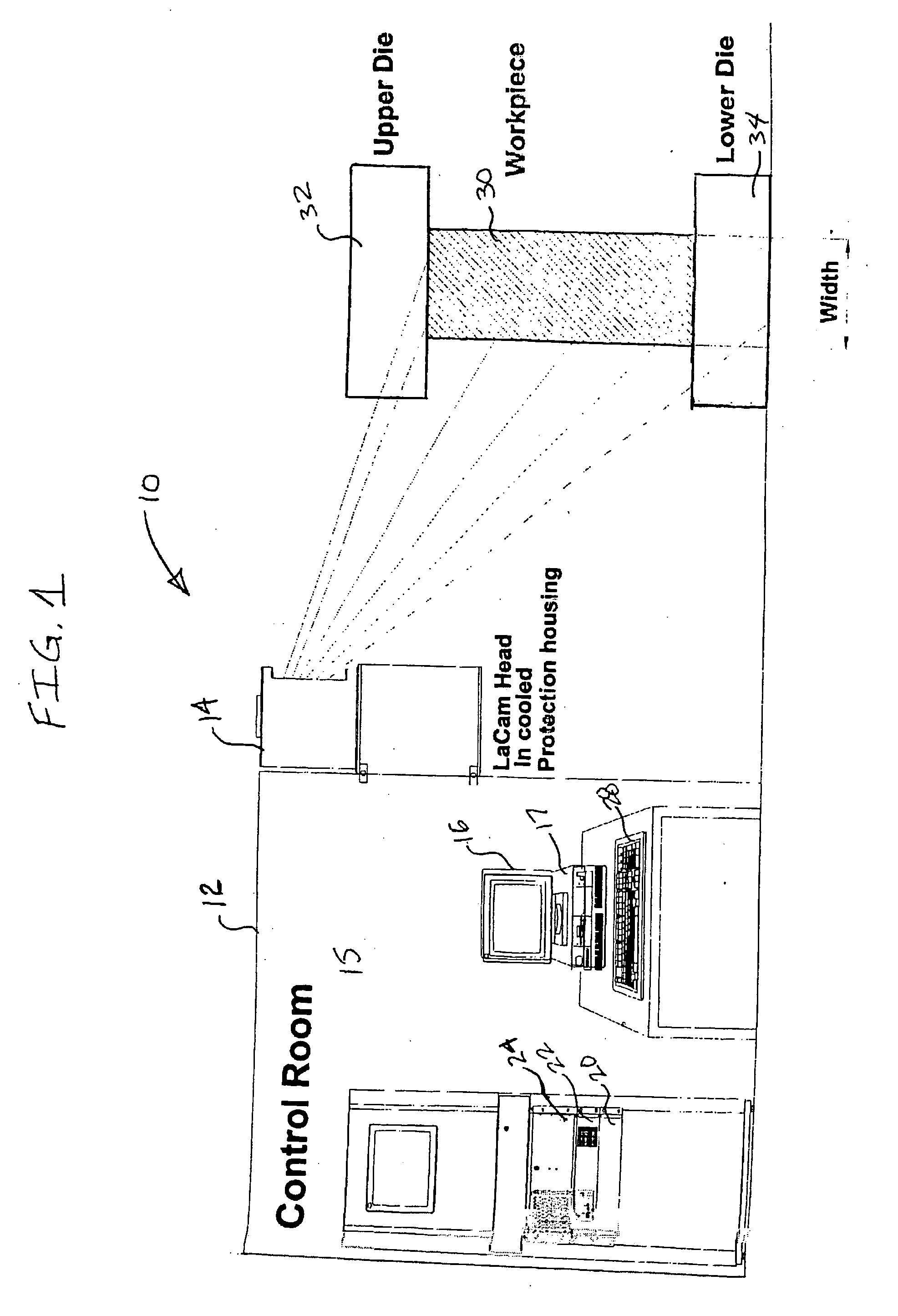
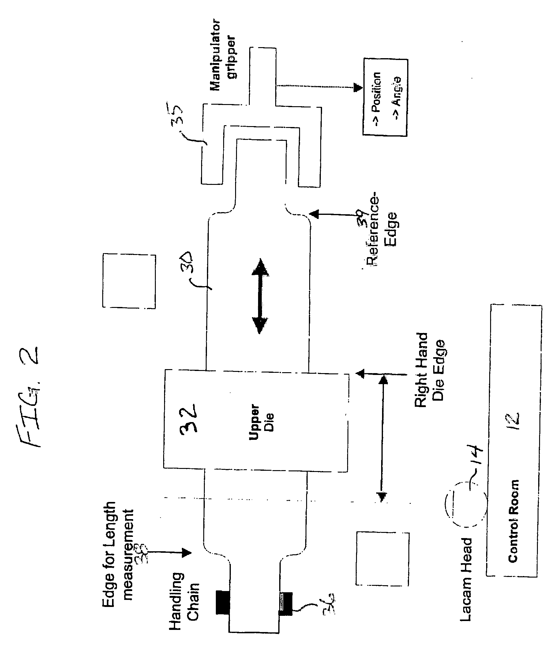
[0015] According to the apparatus and method of the present invention as described herein, a contactless method and apparatus are provided for controlling a forging operation using a contactless laser profile measurement. The method and apparatus are particularly useful in controlling center line consolidation of a workpiece during a cogging operation.

[0016] Briefly, the method of the present invention measures the real-time length of a workpiec...


PUM

PropertyMeasurementUnit
Lengthaaaaaaaaaa
Ratioaaaaaaaaaa
Widthaaaaaaaaaa

Abstract

A method and apparatus for optimizing the forging of a workpiece that is moved along a longitudinal axis of a forging press. The method includes detecting the relative positions of the first and second ends of the workpiece along the longitudinal axis and calculating a length of the workpiece therebetween.

Description

[0001] The use of open die forging to form and / or draw a metallic workpiece between upper and lower dies of a forging press is known, particularly with respect to forging operations of large size workpieces (e.g., for power generation machinery, crank shafts). One important aspect with respect to the quality of a forged product, is a uniform and thorough forging of the core of a workpiece in order to eliminate cavities and other inclusions in the workpiece that impair quality. To achieve a uniform consolidation of the center line, the center line being the direction in which the workpiece is moved forward and backward wherein the center of mass of the workpiece is considered the center line of a workpiece being forged. One process known as “cogging” is used to convert coarse-grained, cast ingot into fine-grained, wrought billet or in other words break down the coarse cast structure and consolidate internal defects in the work piece. In many forging shops, because of various constrai...

Claims


Application Information

Patent Timeline
IPC IPC(8): B21C51/00B21J1/04B21J9/20
CPCB21C51/00B21J9/20B21J1/04
Inventor KIRCHHOFF, STEFAN
Owner SPECIALITY MINERALS (MICHIGAN) INC
Learn More