
Circuit module, and electronic device using the module

A technology for circuit modules and circuit boards, applied in printed circuits, printed circuits, printed circuit manufacturing, etc., can solve problems such as resin outflow, appearance deterioration, and smoothness reduction.

Inactive Publication Date: 2010-07-14
PANASONIC CORP
View PDF1 Cites 0 Cited by
  • Summary
  • Abstract
  • Description
  • Claims
  • Application Information

AI Technical Summary

Problems solved by technology

[0004] In the above structure, the resin can be filled from all sides of the perimeter with respect to the solder balls at the lower surface of the package (to be connected to the motherboard), so the resin directly fills and seals the connection between the solder balls and the motherboard , where poor connections due to peeling become a problem in BGA type IC packages
[0005] In the above structure, there is a limit to the viscosity of the resin that can be used, unless the resin has a certain viscosity, it will cause the resin to flow out from the resin pouring hole, which becomes the cause of flash
On the other hand, when the viscosity is high, the smoothness after curing decreases, so that there is a problem of poor appearance

Method used


Image

  • Circuit module, and electronic device using the module
  • Circuit module, and electronic device using the module
  • Circuit module, and electronic device using the module

Examples


Embodiment 1

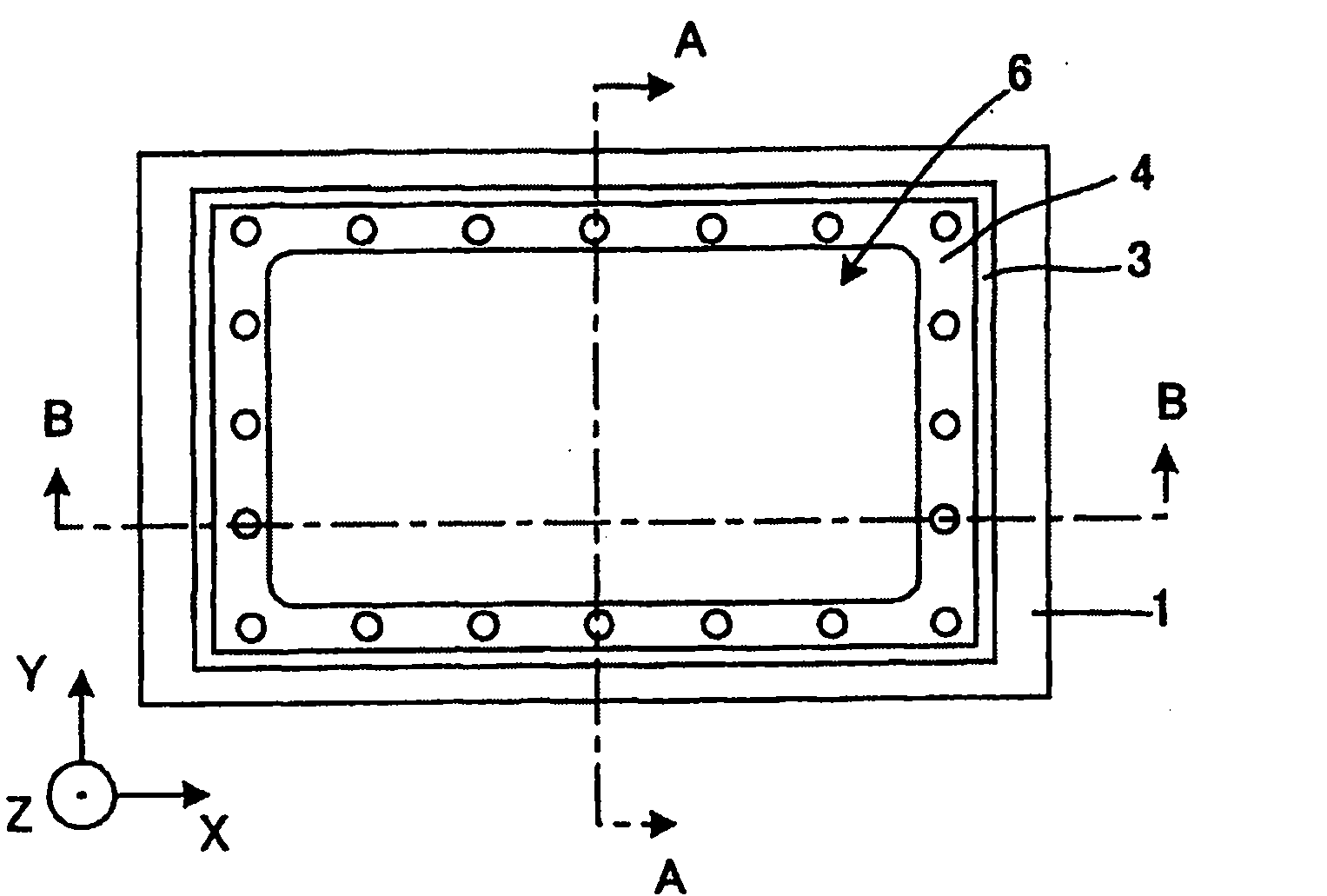
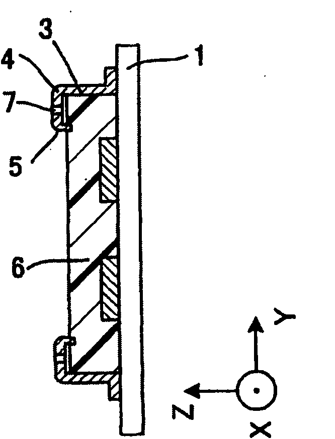
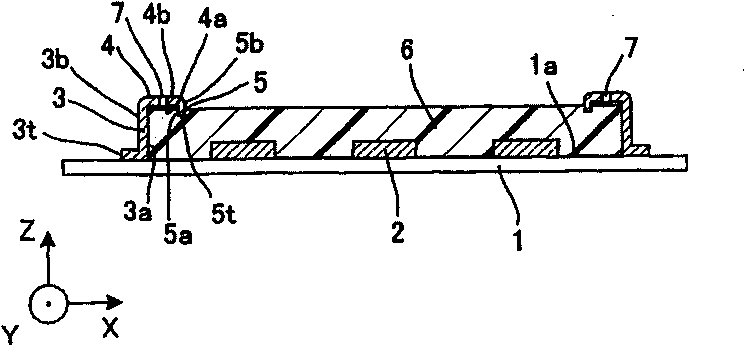
[0110] The circuit module according to Embodiment 1 of the present invention is used in a portable terminal as a portable electronic device, such as Figures 1A to 1C As shown, it is characterized in that the circuit module includes: a circuit board 1 having a wiring pattern (not shown) including at least one external connection terminal (not shown); a plurality of electronic components 2 mounted on one of the circuit board 1 On the surface 1a; the cylindrical main body 3 is provided on the surface 1a in an upright manner so as to surround these electronic components 2 so that a part of the inner surface 3a of the cylindrical main body 3 provided near the first cylindrical end surface 3t is joined to the surface 1a The turnback portion 4 is arranged on the opposite end of the first cylindrical end surface 3t of the cylindrical main body 3, and has a first surface 4a and a second surface 4b opposite to the first surface 4a, the first surface 4a is substantially perpendicular to ...

Embodiment 2

[0124] Next, Embodiment 2 of the present invention will be described.

[0125] The circuit module according to Embodiment 2 of the present invention is used in a portable terminal as a portable electronic device, and is different from the above-described Embodiment 1 in that the end face 3t of the cylindrical main body 3 is bonded to the face 1a of the circuit board 1, and the sealing resin is filled with In the entire internal space surrounded by the inner surface 3a of the cylindrical main body 3, the first surface 4a of the folded part and the first extended inner surface 5a of the extension part 5, no air cavity is formed, such as Figures 3A to 3C shown. With this configuration, a further improvement in surface smoothness and a thinner design can be achieved.

[0126] That is, it is characterized in that it includes: a circuit board 1 having at least one external connection terminal (not shown); a plurality of electronic components 2 mounted on one face 1a of the circuit...

Embodiment 3

[0132] Next, Embodiment 3 of the present invention will be described.

[0133] The circuit module according to Embodiment 3 of the present invention is used in a portable terminal as a portable electronic device, and the only difference from Embodiment 1 is that the circuit module does not have a through hole 7, such as Figures 4A to 4C shown, while other components are formed in a similar manner.

[0134] In this configuration, any through hole is not formed in the turned-back portion extending from the cylindrical body, by doing so, the strength of the turned-back portion 4 can be improved, and the strength of the whole including the cylindrical body and the extension can be improved. In addition, the magnetic shielding effect by the cylindrical body surrounding the electronic component 2 is improved as a matter of course, and the moisture resistance is also improved because no through holes are provided.

[0135] Incidentally, when filling the sealing resin, it is sometim...


PUM


Abstract

Provided is a circuit module comprising a circuit substrate, a plurality of electronic parts mounted on one face of the circuit substrate, a cylindrical member so erected from that face as to enclose the electronic parts, a folded portion folded inward at a predetermined height position of the cylindrical member, and a resin portion constituted of such a sealing resin to cover the electronic parts at least partially in the cylindrical member as is filled to a level to reach the leading end of the folded portion. This constitution joins the sealing resin and the two faces of the folded portion so that it can provide the circuit module which has an increased strength and which is thin but has a high strength. Moreover, through holes are formed in such a region of the folded portion as is exposed from the sealing resin. As a result, it is possible not only to eliminate the cavity, which might otherwise be formed in the folded portion (or the C-shaped portion) by the expansion of the residual gas, but also to suppress the bulge, as might otherwise be created on the upper resin face by the cavity which is formed by the gas moved from the inside of the folded portion to the resin, or the crater-shaped undulations, as might otherwise be created in the upper face of the resin portion when the gas in the frame goes to the upper face of the resin.

Description

technical field [0001] The present invention relates to a circuit module and an electronic device using the circuit module, and more particularly, to a circuit board in which a plurality of electronic parts are mounted (attached) on a circuit formed with wiring conductors It also relates to an electronic device (with portability) using the circuit board, such as a cellular phone and a portable communication terminal. Background technique [0002] A circuit board used in a portable terminal such as a cellular phone includes a substrate on which a circuit pattern is formed and a plurality of electronic components mounted such that terminal portions thereof are fixed to the circuit pattern by solder. [0003] Furthermore, in recent years, among such circuit boards, a structure has been proposed in which the IC package is fixed to the motherboard by providing a reinforcement frame that covers the periphery of the upper surface of the IC package and can be filled with resin. wit...

Claims


Application Information

Patent Timeline
Patent Type & Authority Applications(China)
IPC IPC(8): H05K3/28H05K1/11
CPCH05K3/284H05K2203/1316H05K2201/2018
Inventor 井上胜裕佐佐木智
Owner PANASONIC CORP
Learn More