
Cell necrosis apparatus with cooled microwave antenna

a cell necrosis and microwave antenna technology, applied in the field of tissue microwave thermal therapy, can solve the problem of relatively complex interface module, achieve high flexural moduli, enhance flexural moduli, and minimize the potential for buckling of the probe shaft

Inactive Publication Date: 2005-11-03
TELEFLEX LIFE SCI LTD
View PDF33 Cites 207 Cited by
  • Summary
  • Abstract
  • Description
  • Claims
  • Application Information

AI Technical Summary

Benefits of technology

The present invention is a new microwave generator system for cell necrosis treatment. The system includes a microwave generator, coolant circulation system, and a probe with a coaxial feedline cable and coolant entry / exit passages. The probe has a symmetrical structure and a symmetrical radiation pattern emanating from the antenna assembly. The system also includes a flexible coaxial feedline cable and temperature sensors at the probe tip. The invention provides a new method for cooling the probe to prevent tissue damage and a new method for treating cell necrosis by using a microwave generator system. The technical effects of the invention include improved cooling efficiency, reduced need for sensors, and better tissue heating and ablation.

Problems solved by technology

This interface module is relatively complex as is it constructed to prevent the circulating liquid from physically contacting the sensor control unit, which thus avoids a need for time consuming and expensive cleaning and sterilization of the sensor control unit between patents.

Method used


Image

  • Cell necrosis apparatus with cooled microwave antenna
  • Cell necrosis apparatus with cooled microwave antenna
  • Cell necrosis apparatus with cooled microwave antenna

Examples


Embodiment Construction

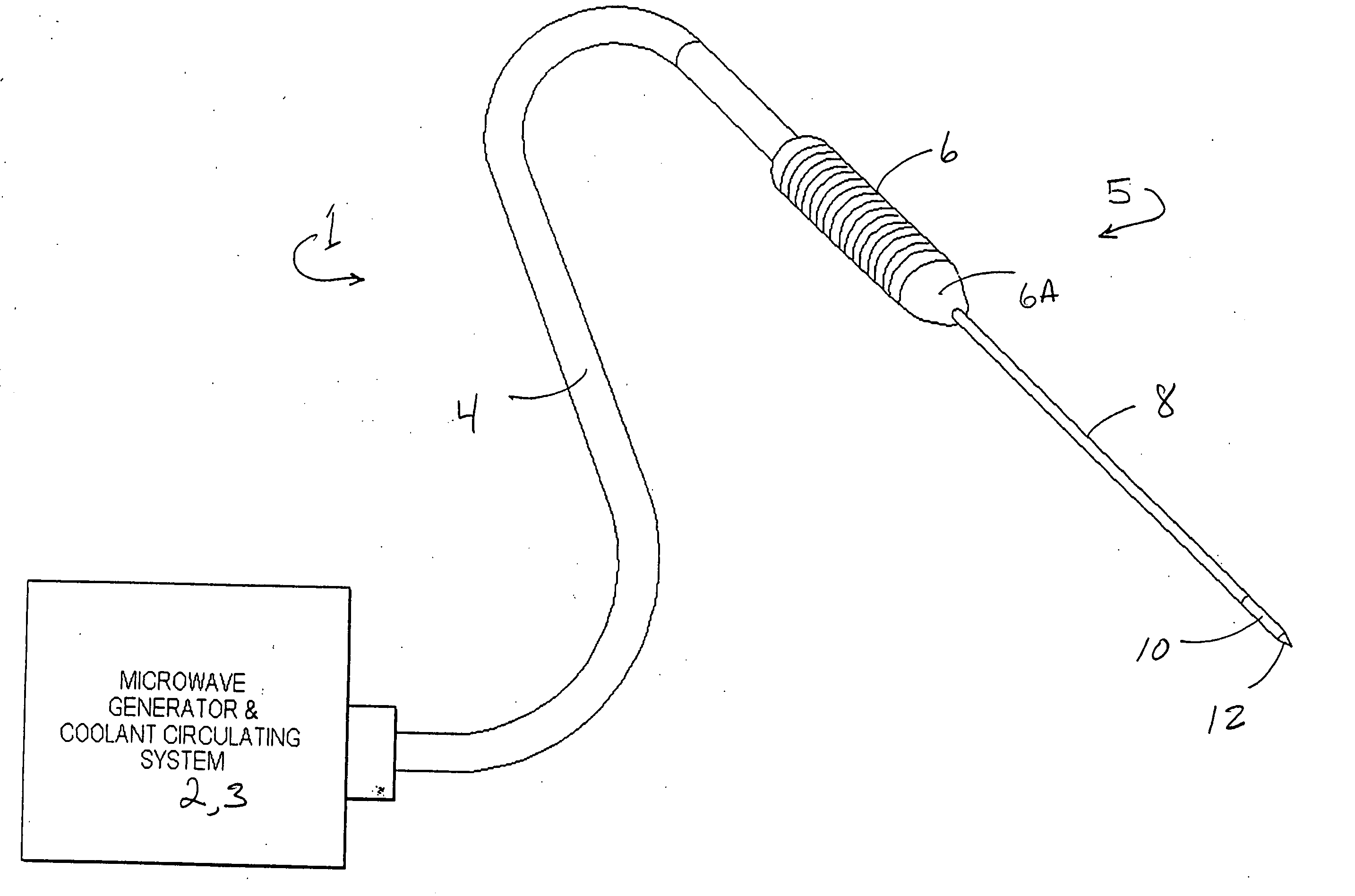
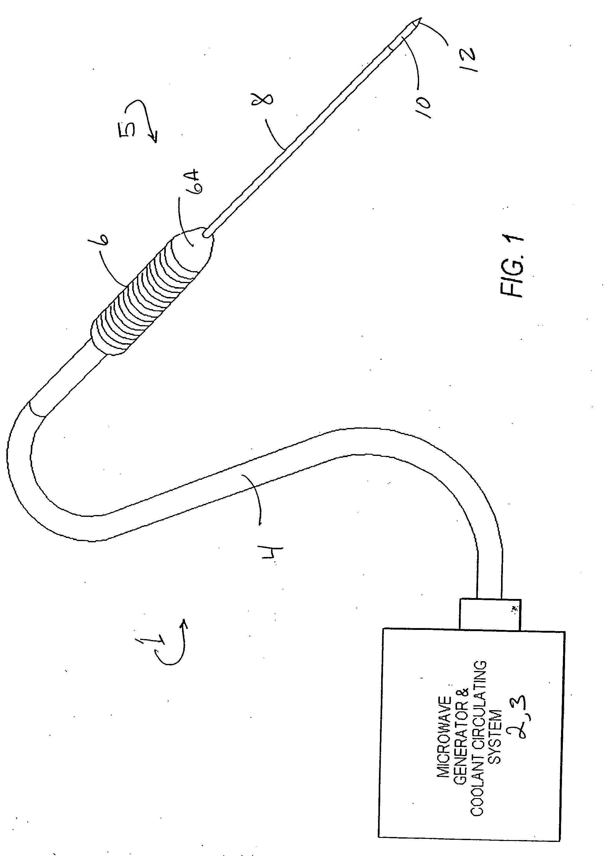
[0058] A preferred embodiment of the new cell necrosis apparatus 1 is seen in FIG. 1 as a combination of a microwave generator 2 and coolant reservoir and circulating apparatus 3, flexible transmission cable 4 including transmission line 18 therein, and probe 5, the probe consisting of probe handle 6, probe body 8, radiating element segment 10 at the distal part of the probe body, and probe tip 12 at the distal end of the probe body. The coolant passageways are configured to flow coolant coaxially in the probe body and about the antenna to produce a symmetrical radiation pattern.

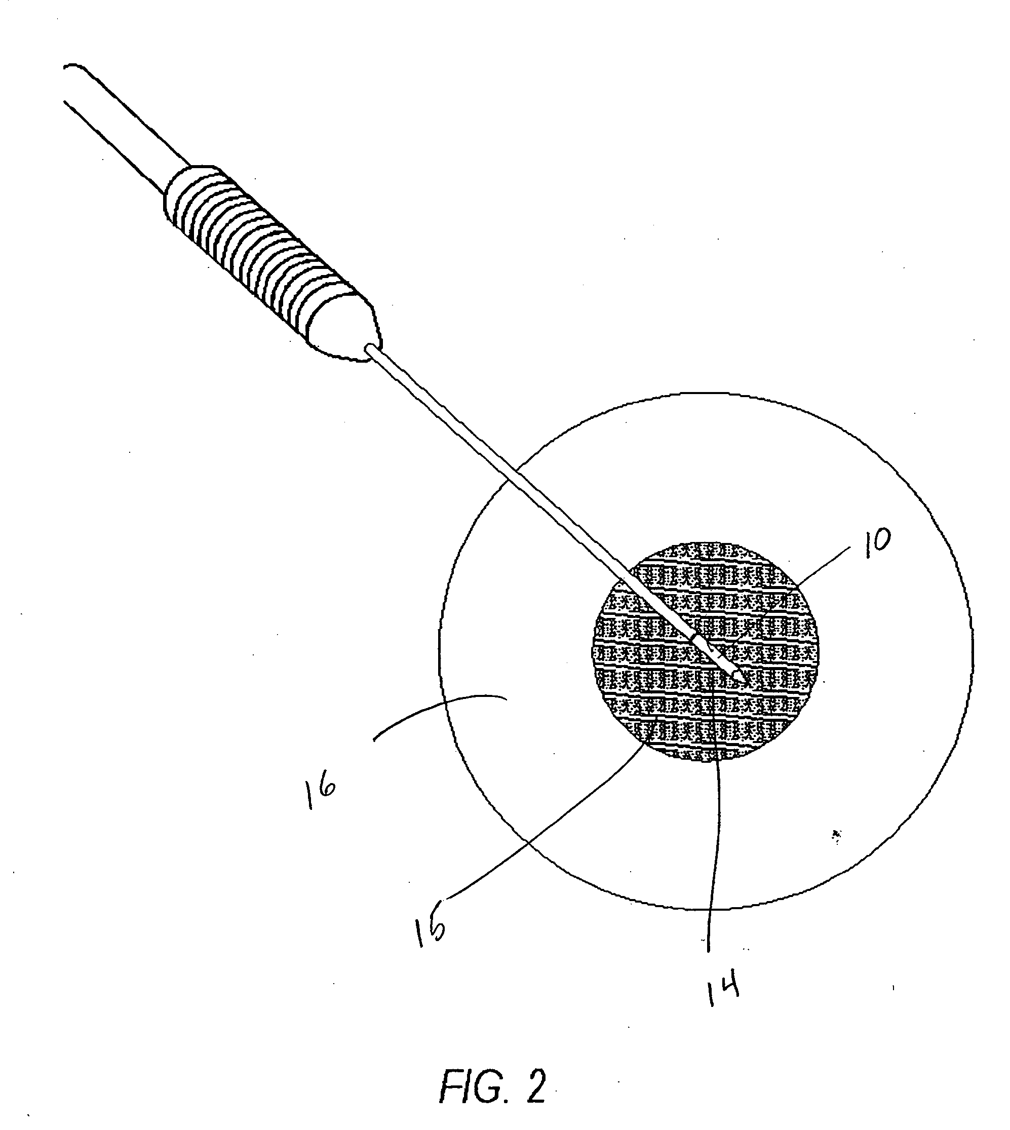
[0059] To better understand the present invention the environment of its use is indicated in FIG. 2 which shows the radiating element segment 10 of probe 5 inserted into the central portion 14 of a tumor mass 15 of an organ system 16. To reach the organ system, the probe first had to penetrate the patient's skin unless the organ system was previously exposed.

[0060] The new cell necrosis apparatus will now ...


PUM


Abstract

A cell necrosis apparatus for delivering thermal microwave energy to a specific site in a body, including: a. a microwave generator, b. a coolant delivery system for delivering and circulating a quantity of cooled liquid coolant via inlet and return passageways, c. a probe including a probe handle and a probe body having a proximal portion coupled to the probe handle and a distal portion, d. a microwave antenna in the distal portion of the probe body for applying thermal microwave energy to a specific site in cell necrosis treatment, and e. a microwave transmission line extending from the microwave generator to and through the probe handle and to and through the probe body to the microwave antenna and electrically coupled thereto, where the inlet and return coolant flow passageways extend from the coolant delivery system to and through the probe handle and thence extend coaxially about the microwave transmission line and along the length thereof within the probe body, and extend coaxially about the antenna and long the length thereof within the probe body, and where a first of the inlet and return coolant flow passageways is radially outward of and immediately adjacent the microwave transmission line and the antenna within the probe body and the other of the inlet flow passageways is radially outward of the first flow passageway.

Description

FIELD OF THE INVENTION [0001] The present invention is in the field of microwave thermal therapy of tissue in a body and more particularly is an apparatus and method for treating interior tissue regions with a cell necrosis probe energized by a microwave generator. BACKGROUND OF THE INVENTION [0002] Cell necrosis apparatus and methods are known in treatment of a variety of organs including but not limited to the prostate, liver, lungs, breasts and kidneys. In regard to prostate treatment, for example, U.S. Pat. No. 5,301,687 to Wong discloses a method and apparatus using an intracavity approach to the prostate through either the rectum or the urethra. [0003] U.S. Pat. No. 5,273,886 to Edwards discloses an RF tissue heating system which includes a cooling feature where liquid coolant is used to cool the tissue being treated. More specifically sterile coolant water is applied to mucosal tissue at the targeted tissue region and subsequently is aspirated. [0004] U.S. Pat. No. 5,733,319 ...

Claims


Application Information

Patent Timeline
Patent Type & Authority Applications(United States)
IPC IPC(8): A61B18/00A61B18/18
CPCA61B18/18A61B2018/00023A61B18/1815
Inventor VITULLO, JEFFREY M.HARDING, MICHAEL R.HARDING, RICHARD L.
Owner TELEFLEX LIFE SCI LTD
Learn More