Magnetic head slider and a magnetic disk device in which the slider is mounted

a slider and magnetic disk technology, applied in the direction of maintaining the head carrier alignment, recording information storage, instruments, etc., can solve the problems of disk damage, disk failure to rotate, serious problems, etc., and achieve the effect of reducing the flying height of the slider, reducing the atmospheric pressure, and high reliability

Inactive Publication Date: 2005-11-03
HITACHI GLOBAL STORAGE TECH JAPAN LTD
View PDF19 Cites 0 Cited by
  • Summary
  • Abstract
  • Description
  • Claims
  • Application Information

AI Technical Summary

Benefits of technology

[0013] It is therefore an object of the present invention to provide a magnetic head slider in which even when the slider is leaned forward, a front edge of each step surface is prevented from being brought into contact with a disk surface, and besides the amount of reduction of the flying height of the slider due to a decrease of the atmospheric pressure is reduced, thereby enabling the reading and writing of data in a stable manner, and to provide a magnetic disk device of a high reliability.

Problems solved by technology

In a device using this CSS system, a so-called sticking problem arises from a smooth disk surface, and more specifically, when the rotation of the disk is stopped, the slider sticks to the disk surface.
When the slider sticks to the disk, there are encountered troubles such as the failure of the disk to rotate.
The front edge of the step surface is sharp, and when this front edge is brought into contact with the disk surface, there arises a problem that the disk is damaged by this front edge.
Particularly in a magnetic disk device of the type in which the flying height of the slider is small, and the smooth disk is used for the purpose of achieving a low flying height, this problem is serious because of the large frictional force.
With this method, however, an opening of the step surface (that is, the distance of the step surface from the disk surface) is large, and an increased amount of dust and dirt enter this opening, which leads to a possibility that the flying height is varied.
When the flying height is thus varied, an error in the data reading and writing operation occurs.
Therefore, this method is not effective in preventing the damage of the disk by the front edge (sharp edge portion) of the step surface.
When the flying height is reduced, there arises a problem that the slider comes into contact with the disk to damage the same.
And besides, when the microscopic projection is provided on the rail of the slider, the reduction of the flying height is, in some cases, limited depending on the height of this projection, so that there is a case that the low flying height design can not be achieved.

Method used


Image

  • Magnetic head slider and a magnetic disk device in which the slider is mounted
  • Magnetic head slider and a magnetic disk device in which the slider is mounted
  • Magnetic head slider and a magnetic disk device in which the slider is mounted

Examples


first embodiment

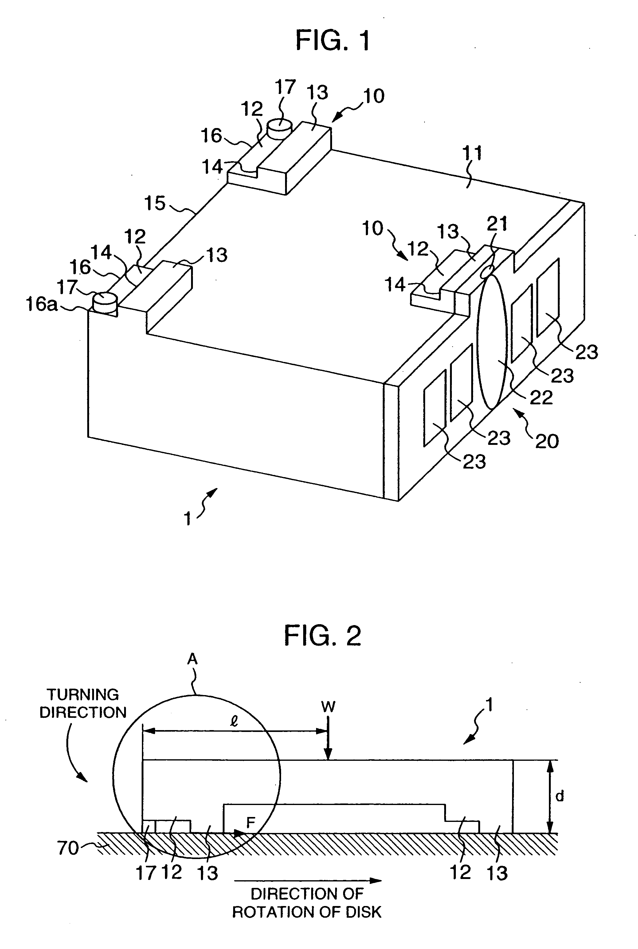
[0030] the present invention will now be described with reference to FIGS. 1 to 6 and FIG. 14.

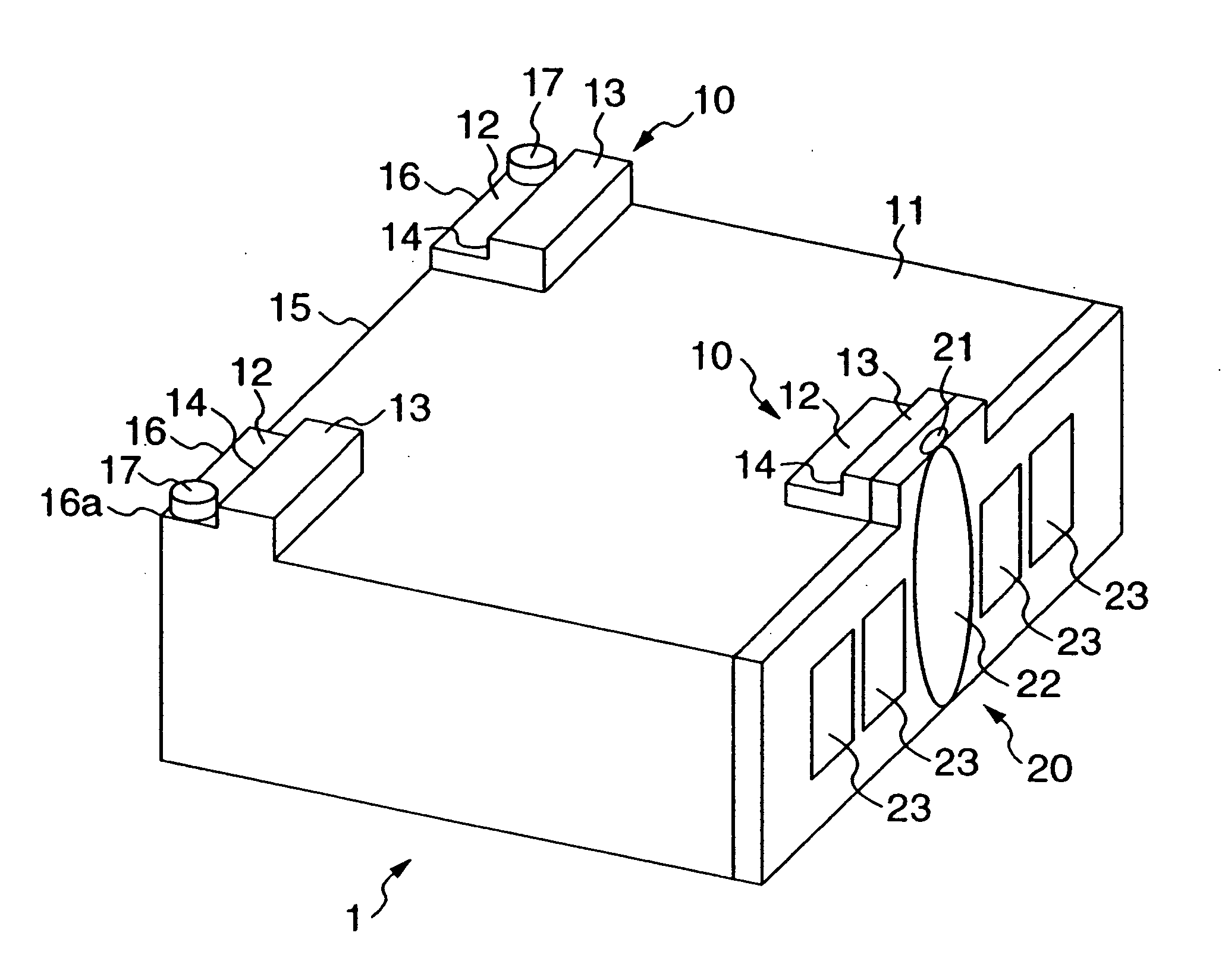
[0031]FIG. 1 is a perspective view of one embodiment of a slider of the invention, showing a flying surface thereof.

[0032] Three pads for flying 10 for producing a flying force are formed on a bleed surface 11 of the slider 1. Two of these pads 10 are provided respectively at opposite ends of an inflow-side portion (to which an air stream, produced in accordance with the rotation of a disk, flows) of the slider 1, and the other pad 10 is provided at a central portion of an outflow-side portion of the slider 1. Each flying pad 10 has a flat surface portion 13, a step portion 14 (defined by a surface disposed generally perpendicular to the flat surface portion 13) facing the air stream inflow side, and a step surface 12. The flat surface portions 13 of the three flying pads 10 lie generally in a common horizontal plane. The step surface 12 is disposed generally parallel to the flat surface p...


PUM

PropertyMeasurementUnit
heightaaaaaaaaaa
surface roughnessaaaaaaaaaa
thicknessaaaaaaaaaa

Abstract

A magnetic head slider includes a magnetic head for recording/reproducing information from/into a magnetic disk and a slider on which the magnetic head is mounted. The slider has a first positive pressure generating portion provided at an air-inflow side and a positive pressure generating portion surface provided at an air-outflow side, projections being provided at the air-inflow side at positions with respect to the first positive pressure generating portion on a first surface which faces the magnetic disk upon read/write operation of the magnetic head slider, and a step surface provided at the air-inflow side with respect to said first positive pressure generating portion.

Description

CROSS REFERENCE TO RELATED APPLICATION [0001] This is a continuation of U.S. application Ser. No. 10 / 618,760, filed Jul. 15, 2003, which is a continuation of U.S. application Ser. No. 10 / 217,439, filed Aug. 14, 2002, now U.S. Pat. No. 6,597,537, which is a continuation of U.S. application Ser. No. 10 / 102,679, filed Mar. 22, 2002, now U.S. Pat. No. 6,452,751,which is a continuation of U.S. application Ser. No. 09 / 299,909, filed Apr. 28,1999, now U.S. Pat. No. 6,373,661, the subject matter of which is incorporated by reference herein.BACKGROUND OF THE INVENTION [0002] 1. Field of the Invention [0003] The present invention relates to a magnetic head slider for a magnetic disk device and also to a magnetic disk device, and more particularly to a magnetic head slider of a low flying height-type for achieving high reliability and high-density recording and also to a magnetic disk device having such a magnetic head slider. [0004] 2. Description of the Related Art [0005] In magnetic disk de...

Claims


Application Information

Patent Timeline
Patent Type & Authority Applications(United States)
IPC IPC(8): G11B5/60
CPCG11B5/6005G11B5/60G11B5/6082
Inventor TOKUYAMA, MIKIOISHII, MIEKOTSUCHIYAMA, RYUJIKAWAKUBO, YOUICHITOKISUE, HIROMITSU
Owner HITACHI GLOBAL STORAGE TECH JAPAN LTD
Why Eureka
Try Eureka