
Apparatus for removing liquid in immersion lithography process and method of immersion lithography

a technology of immersion lithography and apparatus, which is applied in the direction of lighting and heating apparatus, printing equipment, instruments, etc., can solve the problems of high equipment requirements, defects during patterning process, and difficulty or inability to remove immersion lithography liquid remaining on the substrate before development and after exposure, so as to achieve rapid and easy removal of immersion lithography liquid

Inactive Publication Date: 2005-11-03
DONGBU ELECTRONICS CO LTD
View PDF15 Cites 29 Cited by
  • Summary
  • Abstract
  • Description
  • Claims
  • Application Information

AI Technical Summary

Benefits of technology

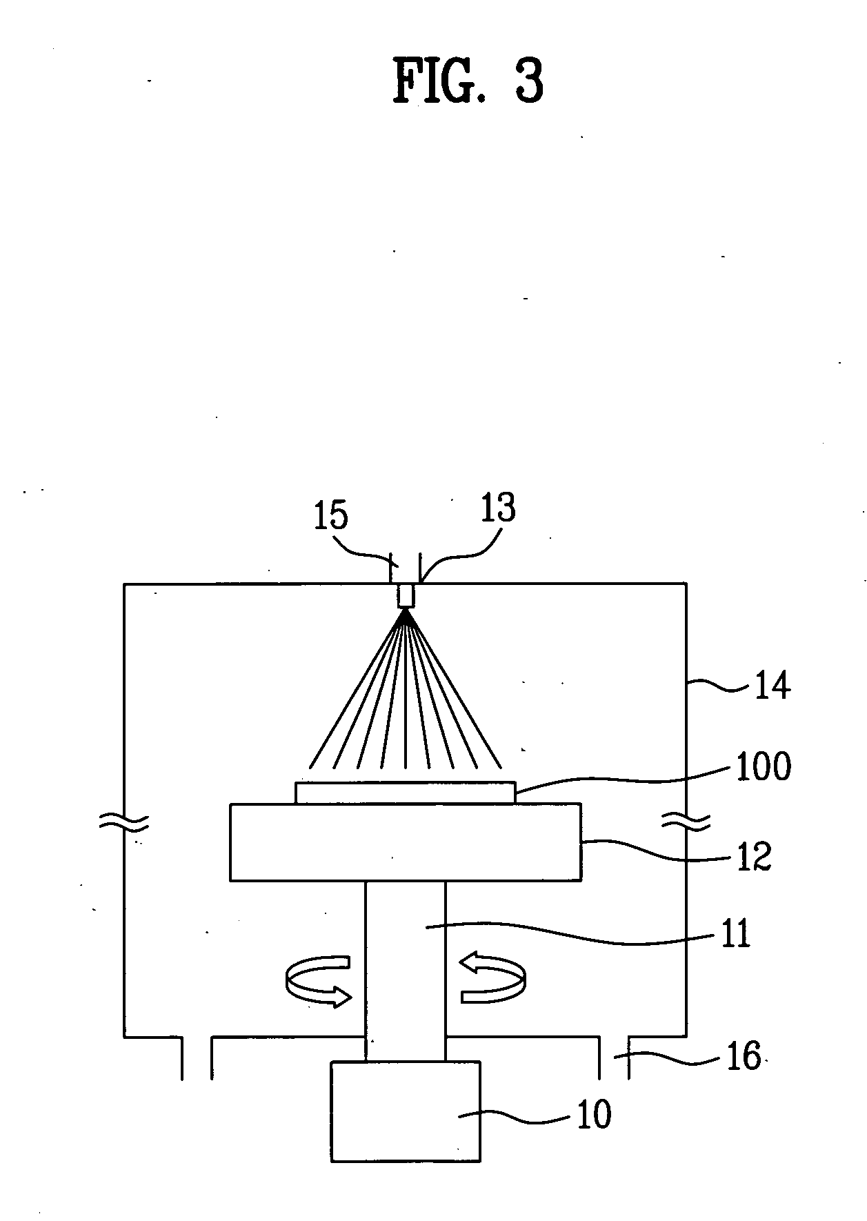
The present invention provides apparatuses and methods for removing liquid in an immersion lithography process. The apparatus includes a housing device, a rotatable stage, and a motor for quickly and easily removing the liquid from a substrate after exposure. The method includes coating the substrate with photoresist, immersing it in a liquid, exposing it, and then removing the liquid by spraying it with an inert gas while the substrate is rotating. The technical effects of the invention include reducing the risk of contamination, improving the accuracy of the process, and increasing the efficiency of the process.

Problems solved by technology

However, the aforementioned lithography technologies tend to require high-priced equipment.
For example, in the related art immersion lithography process, it is difficult or impossible to remove the immersion liquid remaining on the substrate before development and after exposure.
Accordingly, the liquid remaining on the substrate may react with the photoresist, or may distill or evaporate during the PEB process so that spots form on a wafer, thereby causing defects during the patterning process.

Method used


Image

  • Apparatus for removing liquid in immersion lithography process and method of immersion lithography
  • Apparatus for removing liquid in immersion lithography process and method of immersion lithography
  • Apparatus for removing liquid in immersion lithography process and method of immersion lithography

Examples


Embodiment Construction

[0029] Reference will now be made in detail to the following preferred embodiments of the present invention, examples of which are illustrated in the accompanying drawings. Wherever possible, the same reference numbers will be used throughout the drawings to refer to the same or like parts.

[0030] Hereinafter, an apparatus and method for removing liquid from a wafer in an immersion lithography process according to the present invention will be described with reference to the accompanying drawings.

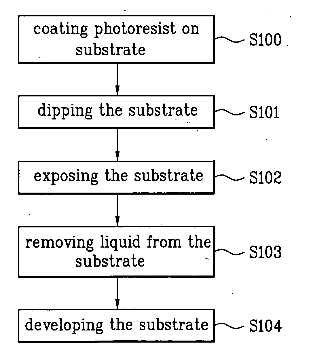
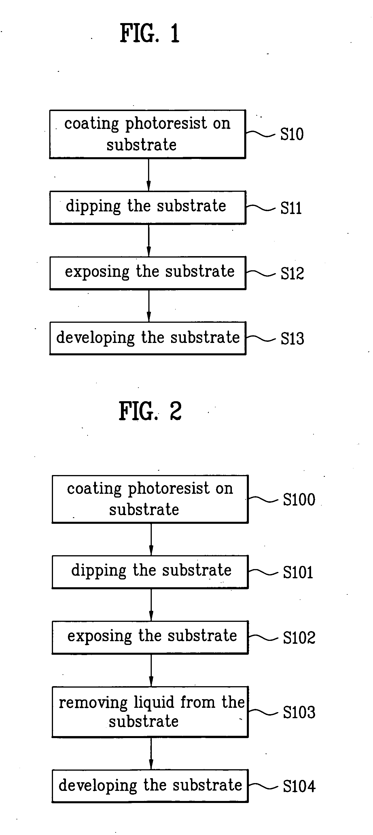
[0031]FIG. 2 is a flowchart of an immersion lithography process according to the present invention. First, a photoresist is coated on a substrate (S100). Then, after soft-baking the photoresist coated on the substrate, the substrate is immersed in a liquid (S101). For example, preferably, the liquid comprises or consists essentially of water (e.g., deionized and / or distilled water, which may further contain one or more salts known to increase the refractivity of water but which do not abso...


PUM

PropertyMeasurementUnit
wavelengthaaaaaaaaaa
rotary poweraaaaaaaaaa
speedaaaaaaaaaa

Abstract

An apparatus for removing an immersion lithography liquid and a method of immersion lithography are disclosed, that rapidly and easily remove liquid from a wafer before development and after exposure. The apparatus includes a housing device configured to prevent the exposure chamber from being contaminated with a scattered liquid; a (rotatable) stage inside the housing device, configured to support a substrate; and (i) a motor configured to rotate the stage or (ii) a gas-spraying device or nozzle above the stage, configured to spray the substrate with an inert gas. The method generally includes coating a photoresist on a substrate; immersing the substrate in a liquid; exposing the substrate; removing the liquid from the substrate by (i) rotating the stage and / or substrate or (ii) spraying the substrate with an inert gas; and developing the photoresist.

Description

CROSS-REFERENCE TO RELATED APPLICATIONS [0001] This application claims the benefit of Korean Application No. P2004-29336 filed on Apr. 28, 2004, which is hereby incorporated by reference as if fully set forth herein. BACKGROUND OF THE INVENTION [0002] 1. Field of the Invention [0003] The present invention relates to apparatuses configured to remove liquid in an immersion lithography process and methods of immersion lithography, and more particularly, to such apparatuses and methods that remove immersion lithography liquid from a wafer before development and after exposure. [0004] 2. Discussion of the Related Art [0005] With the recent development in the information media such as computers, technology for manufacturing semiconductor devices has also developed rapidly. Accordingly, the semiconductor device has been researched and studied to obtain high integration, a minute pattern and a rapid operation speed. Development of a minute pattern technology such as lithography improves the...

Claims


Application Information

Patent Timeline
Patent Type & Authority Applications(United States)
IPC IPC(8): H01L21/027G03B27/52G03F7/20
CPCG03F7/70341G03F7/70983G03F7/70866B26F1/32F25C5/043
Inventor KIM, JIN YOUP
Owner DONGBU ELECTRONICS CO LTD
Learn More