
Low dropout voltage regulator providing adaptive compensation

a voltage regulator and low dropout technology, applied in the field of low dropout voltage regulators, can solve the problems of significantly sensitive poles or pole-zero pairs to operating temperature, prone to instability, and the voltage regulators do not convert power very efficiently, and achieve the effect of optimizing the bandwidth and speeding up the transition respons

Inactive Publication Date: 2005-11-03
SEMICON COMPONENTS IND LLC
View PDF3 Cites 34 Cited by
  • Summary
  • Abstract
  • Description
  • Claims
  • Application Information

AI Technical Summary

Benefits of technology

The present invention provides an adaptive compensation scheme for a low dropout (LDO) voltage regulator that can serve a variety of load conditions. The LDO voltage regulator has improved transient response and stability. The compensation network and the bias transistor generate the pole-zero pairs to achieve a maximum 45 degrees phase shift before reaching the crossover frequency in the LDO voltage regulator. The feedback loop of the LDO voltage regulator is inherently stable and not affected by load conditions. The pole-zero pairs generated in the LDO voltage regulator are adaptively adjusted according to load conditions so that the bandwidth is optimized and a faster transition response is achieved.

Problems solved by technology

Although LDO voltage regulators do not convert power very efficiently, they are inexpensive, small, and generate very little frequency interference.
One problem with the conventional LDO circuits described above is that they are prone to be unstable.
Unfortunately, the pole or the pole-zero pair is significantly sensitive to operating temperature, and possibly to other factors.
If the load impedance varies by a specific amount, an unstable feedback loop may be incurred.
Another problem with the conventional LDO voltage regulators is that a transient response thereof is slow.
The conventional LDO voltage regulator is prone to unstable because the output impedance is various.
Furthermore, performance thereof suffers from slow response.

Method used


Image

  • Low dropout voltage regulator providing adaptive compensation
  • Low dropout voltage regulator providing adaptive compensation
  • Low dropout voltage regulator providing adaptive compensation

Examples


Embodiment Construction

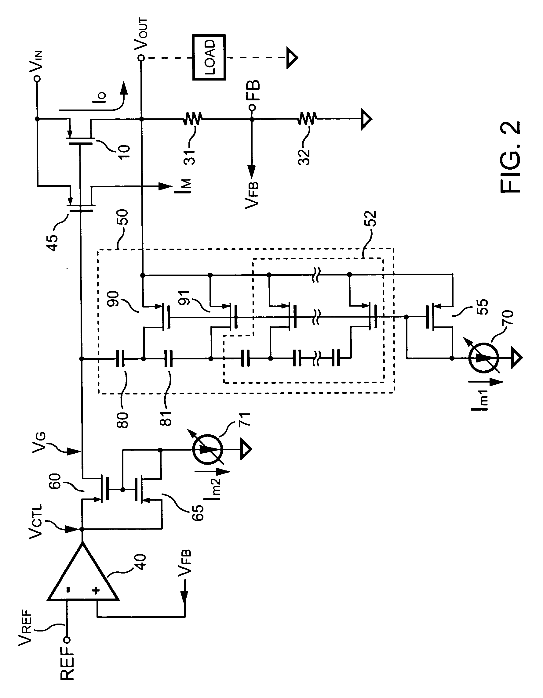
[0022] Referring to FIG. 2, a basic scheme of an LDO voltage regulator circuit according to a preferred embodiment of the present invention is illustrated. The LDO voltage regulator circuit includes an output pass transistor 10, a mirror transistor 45, a compensation network 50 and an error amplifier 40. An unregulated DC input terminal VIN is connected to a source of the output pass transistor 10 and a source of the mirror transistor 45. An output current IO is provided from a drain of the output pass transistor 10 that is coupled to a regulated DC output terminal VOUT. A gate of the mirror transistor 45 and a gate of the output pass transistor 10 are coupled to each other.

[0023] A mirror current IM is generated from a drain of the mirror transistor 45 in proportion to the output current IO. A control voltage VCTL is supplied from an output of the error amplifier 40. The gate of the output pass transistor 10 is operated with a control voltage VG that is supplied from a drain of a ...


PUM


Abstract

A method and apparatus to dynamically modify internal compensation of a low dropout (LDO) voltage regulator is provided. The LDO voltage regulator includes an output pass transistor, an error amplifier, a bias transistor and a compensation network. The compensation network is connected between a gate and a drain of the output pass transistor to compensate for the feedback loop. The compensation network and the bias transistor generate pole-zero pairs to perform a maximum 45 degrees phase shift before reaching the crossover frequency in the LDO voltage regulator. Therefore a minimum 45 degrees phase margin is provided for the feedback loop in various load conditions. Furthermore, the pole-zero pairs produced in the LDO voltage regulator are adaptively adjusted according to load conditions, so that the bandwidth is optimized and faster transient response is achieved.

Description

BACKGROUND OF THE INVENTION [0001] 1. Field of Invention [0002] The present invention relates to a voltage regulator circuit, and more particularly to a low dropout voltage regulator. [0003] 2. Description of the Related Art [0004] Low dropout (LDO) voltage regulators are commonly used in power management systems of PC motherboards, laptop computers, mobile phones, and many other products. Power management systems use LDO voltage regulators as local power supplies, where a clean output and a fast transient response are required. LDO voltage regulators enable power management systems to efficiently supply additional voltage levels that are smaller than the main supply voltage. For example, 5V power systems of many PC motherboards use LDO voltage regulators to supply local chipsets with a clean 3.3V signal. [0005] Although LDO voltage regulators do not convert power very efficiently, they are inexpensive, small, and generate very little frequency interference. Furthermore, an LDO volt...

Claims


Application Information

Patent Timeline
Patent Type & Authority Applications(United States)
IPC IPC(8): G05F1/40G05F1/575H02M3/00
CPCG05F1/575
Inventor YANG, TA-YUNGLIN, JENN-YU G.CHEN, CHIEN-LIANG
Owner SEMICON COMPONENTS IND LLC
Learn More