Gas pin for thermocouple for gas assisted injection molding

a technology of gas assisted injection molding and thermocouple, which is applied in the field of gas pins to achieve the effect of improving and facilitating the injection molding process

Inactive Publication Date: 2005-11-03
INT AUTOMOTIVE COMPONENTS GRP NORTH AMERICA INC
View PDF20 Cites 3 Cited by
  • Summary
  • Abstract
  • Description
  • Claims
  • Application Information

AI Technical Summary

Benefits of technology

[0009] It is also an object of the present invention to provide an improved method and system for injection molding plastic parts with structural rib members and the like, particularly elongated members. It is a further object of the present invention to provide a gas-assisted injection molded system and process in which the introduction of gas and plastic in the mold are controlled in order to provide a satisfactory product in an improved and more beneficial manner.

Problems solved by technology

This is often unreliable and is limited by the condition of the molding machine and any wear properties of its components.

Method used


Image

  • Gas pin for thermocouple for gas assisted injection molding
  • Gas pin for thermocouple for gas assisted injection molding
  • Gas pin for thermocouple for gas assisted injection molding

Examples


Embodiment Construction

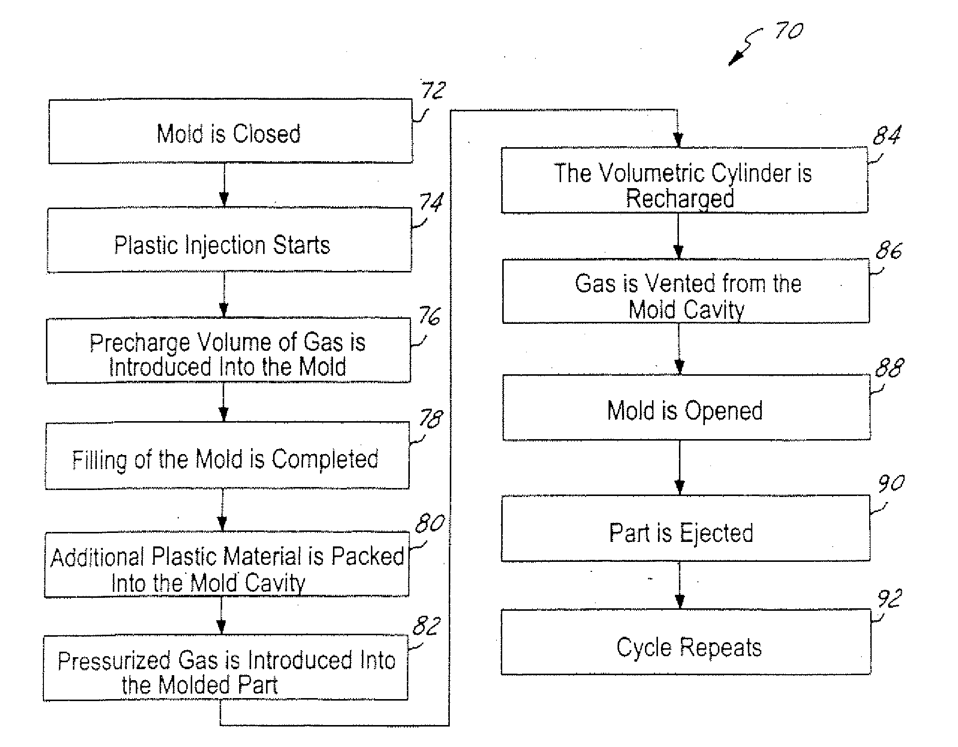
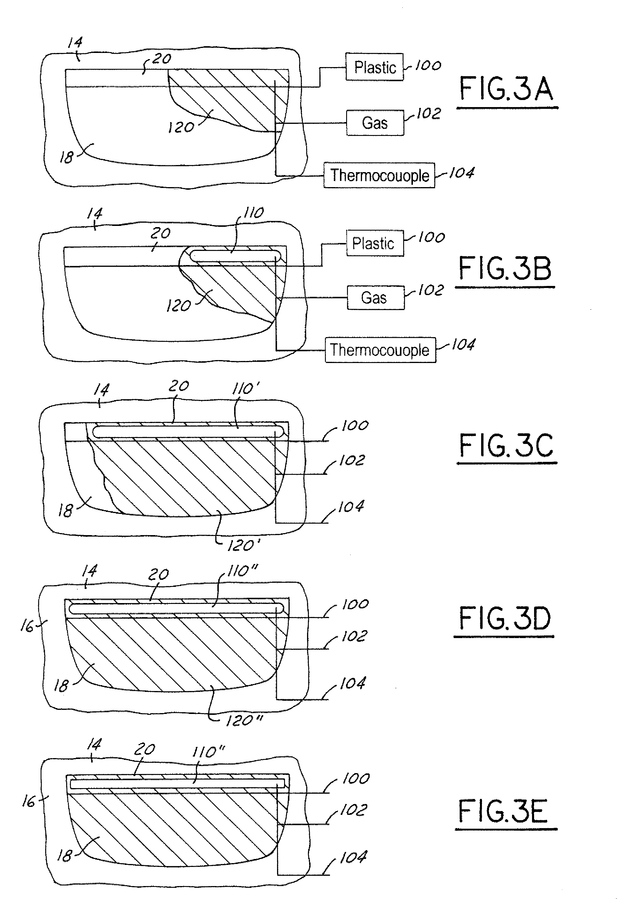
[0028] The present invention is particularly suitable for providing hollow rib structures for structural reinforcement of decorative or non-decorative trim components and panels using gas-assisted plastic injection molding systems and processes. A process for use of the present invention is shown in the drawings. In this regard, even though the present invention is illustrated and disclosed in accordance with one or more preferred embodiments of the inventive system and process, and is described for use with rib structures, it is to be understood that the present invention is not limited to such preferred embodiments or uses. Instead, the present invention should be entitled to the scope afforded to it by the following description and appended claims.

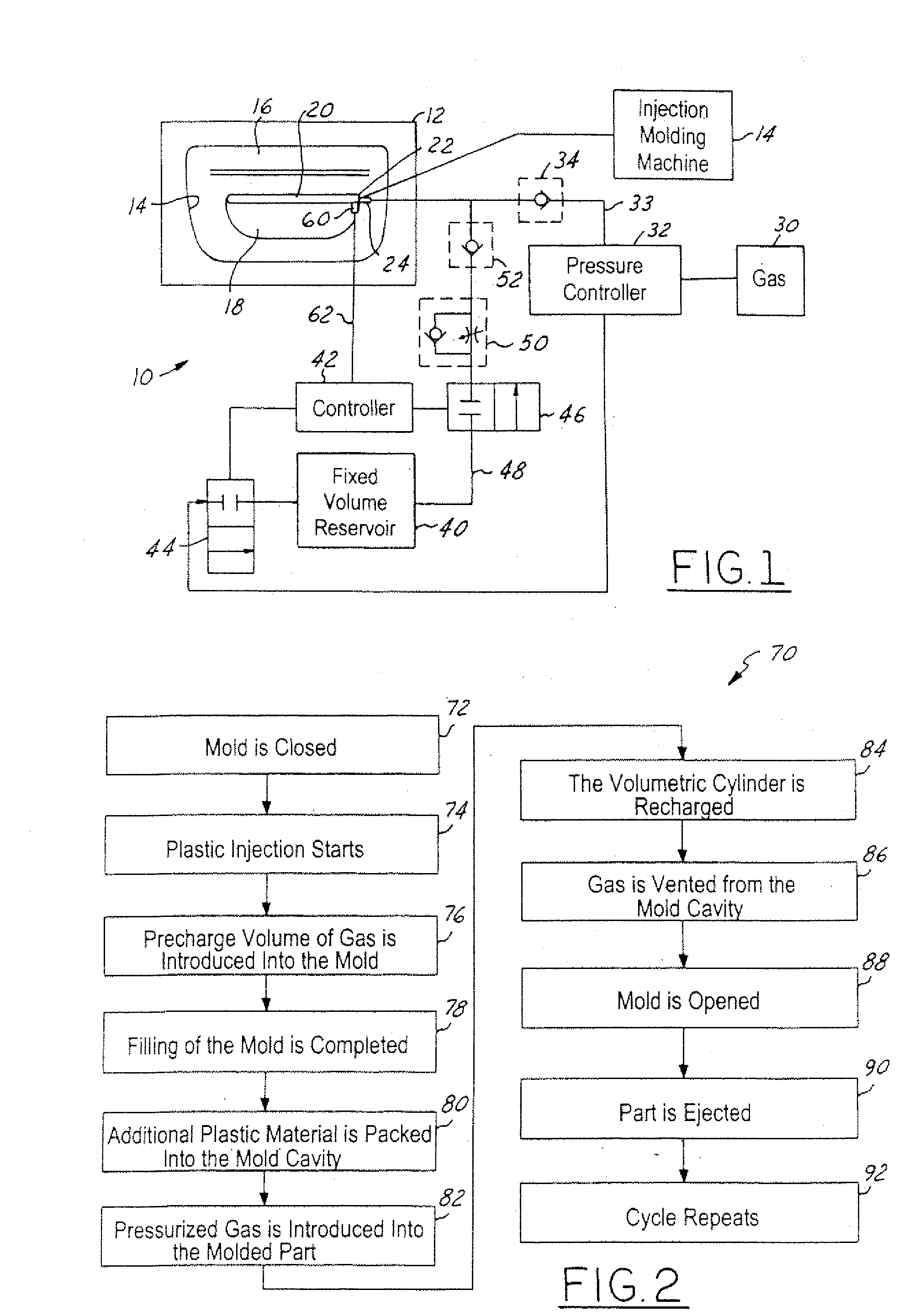
[0029] The system 10 shown in FIG. 1 includes a mold 12 which is positioned in and part of an injection molding machine 14. As is commonly known in the art, there are a number of injection molding machines which can be used to inject p...


PUM

PropertyMeasurementUnit
volumeaaaaaaaaaa
temperatureaaaaaaaaaa
pressureaaaaaaaaaa

Abstract

A method and system for forming an injection molded plastic part. After the injection of plastic material has started, a volume of gas from a fixed volume reservoir is introduced into the plastic material at a low pressure forming a hollow cavity. The gas is introduced into the mold by a gas pin having a temperature sensing device, such as a thermocouple, positioned on it. The introduction of this volume of gas is initiated when the temperature of the plastic material in the mold has reached a predetermined value. After the mold is filled and packed with plastic, pressurized gas is introduced into the hollow cavity forming the completed plastic part.

Description

CROSS REFERENCE TO RELATED APPLICATIONS [0001] This subject matter is related to U.S. patent application Ser. No. ______, entitled “Gas Assisted Injection Molding With Fixed Volume Gas Reservoir and Temperature Control” (Docket No. LC 0149 PUS), which is filed on the same date herewith and the subject matter of which is hereby incorporated by reference herein.BACKGROUND OF INVENTION [0002] The present invention relates to plastic injection molding systems and more particularly to gas pins for use in gas-assisted injection molding systems. [0003] There are numerous known systems for plastic injection molding. In conventional plastic injection molding systems, plastic pellets are melted in an injection molding machine and advanced by a screw ram into a mold cavity, typically through one or more sprue bushings, a manifold, and / or a hot runner system. The mold cavity is formed between two mold halves (a core member and a cavity member). The two halves of the mold are clamped, typically ...

Claims


Application Information

Patent Timeline
Patent Type & Authority Applications(United States)
IPC IPC(8): B29C45/00B29C45/17B29C45/76B29C45/78B29C49/60B29C49/78B29D11/00B29D22/00
CPCB29C45/1734B29C45/78B29C2945/7604B29C2945/76167B29C2945/76244B29C2945/76257B29D11/00413B29C2945/76498B29C2945/76531B29C2945/76545B29C2945/76591B29C2945/76779B29C2945/76287
Inventor HOMANN, GREGORY A.HENDRY, JAMES
Owner INT AUTOMOTIVE COMPONENTS GRP NORTH AMERICA INC
Why Eureka
Try Eureka