
Arrangement for a wire section of a paper or board machine

Inactive Publication Date: 2005-11-03
PACT XPP TECH +1
View PDF3 Cites 3 Cited by
  • Summary
  • Abstract
  • Description
  • Claims
  • Application Information

AI Technical Summary

Benefits of technology

[0011] One object of the invention is also to create a wire section by means of which a higher dry solids content is achieved before a press section, thus making it possible to shorten the wire section. Alternatively, the arrangement in accordance with the invention enables the running speed of the paper machine to be increased in wire section rebuilds.
[0012] The arrangement in accordance with the invention makes it possible to replace the traditionally used, large and expensive suction roll of the wire section with a smaller and less expensive suction roll because the force acting then on the suction roll is lower than in conventional arrangements.
[0013] In accordance with the invention, a suction box, in which the deck or blades of the suction box can be adjusted to be curved at least in a running situation or the wire run in the area of the suction box is curved, is placed in connection with a suction roll, which makes it possible to control the asymmetry of dewatering and, in addition, a higher dry solids content is imparted to the web before a press section, so that it is possible to shorten the wire section, when desired, because it is possible, for example, to omit one suction box situated on the run of the wire since the dewatering capacity increases when the arrangement in accordance with the invention is used.
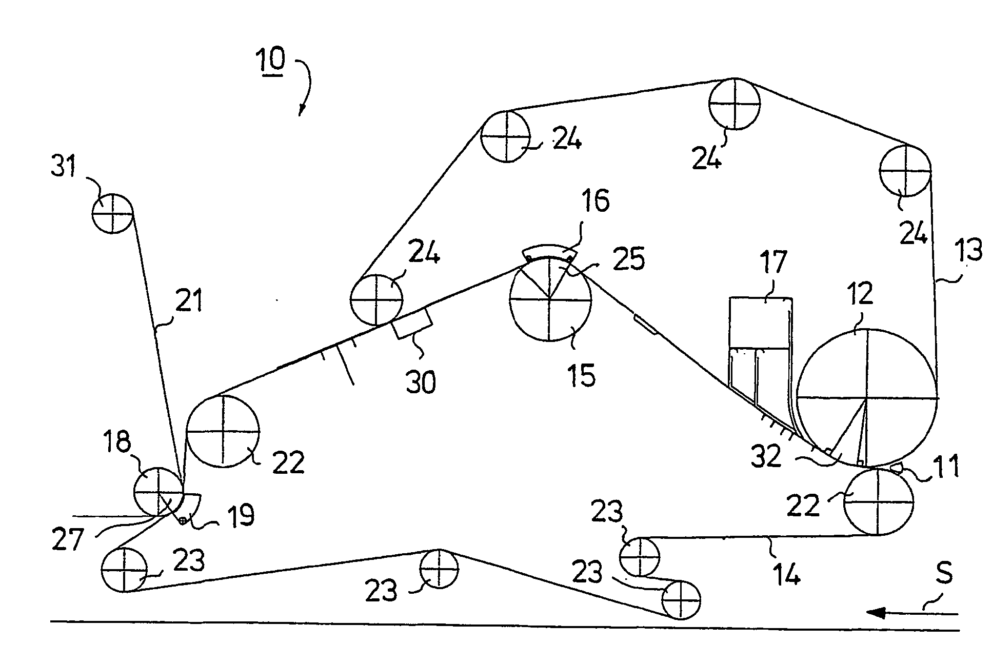
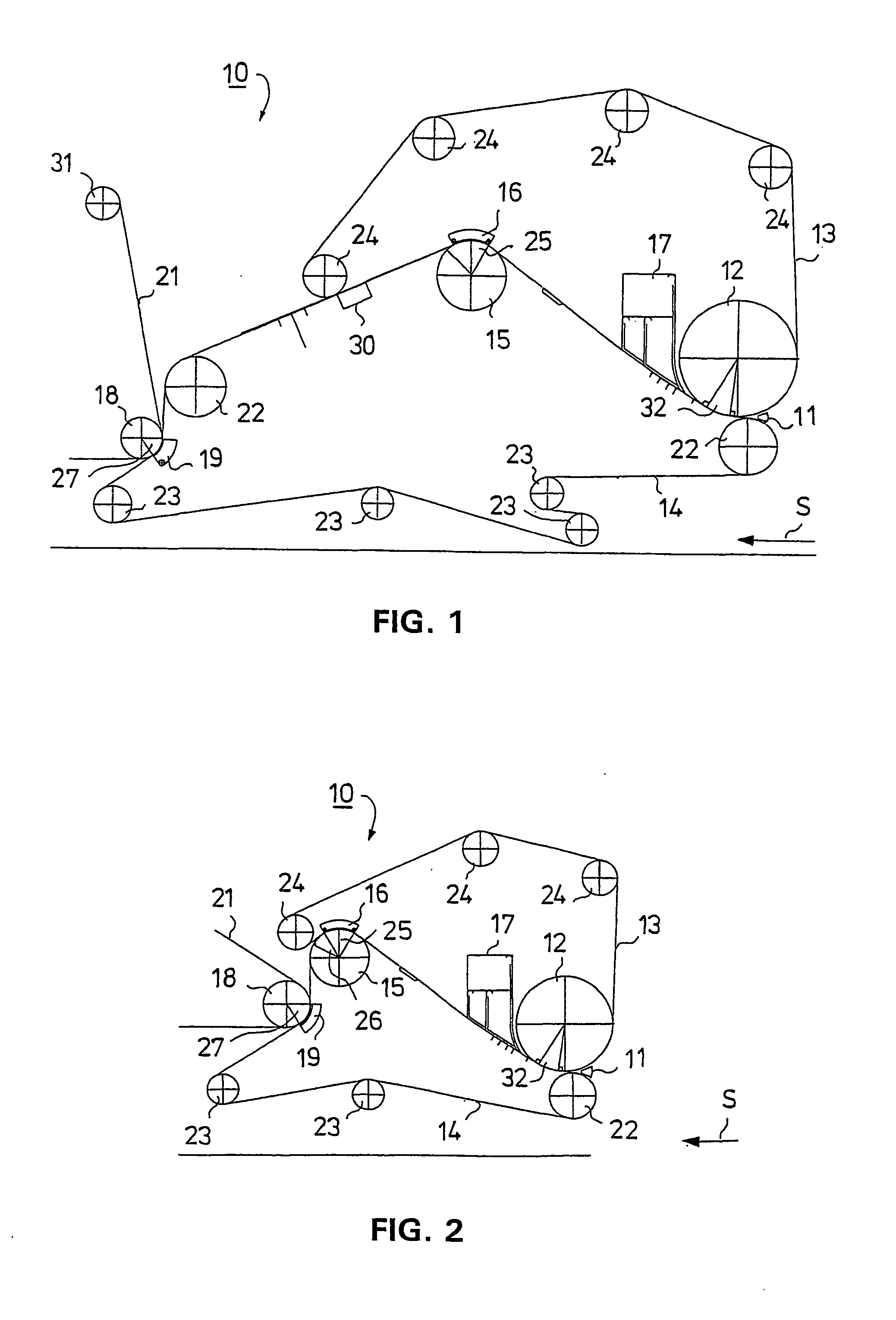
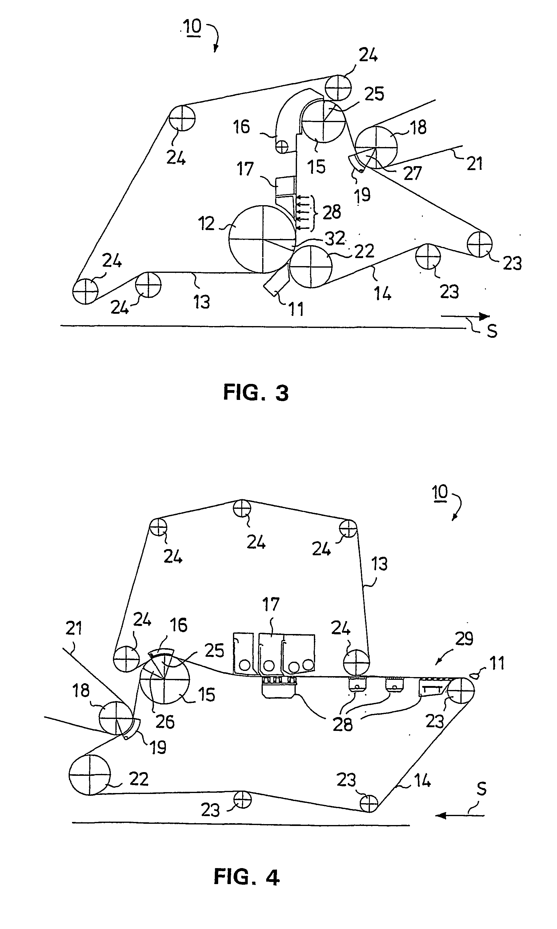
[0018] In the arrangement in accordance with the invention, a curved surface suction box is thus placed on the side of the upper wire loop, thereby achieving a better distribution of dewatering because in the prior art applications the distribution of dewatering of a web has generally been asymmetric, and the arrangement in accordance with the invention makes it possible to improve the distribution of dewatering because a curved surface suction box is placed on the opposite side of the web with respect to the suction roll, thereby allowing dewatering to be regulated in both directions. The arrangement in accordance with the invention thus provides a more uniform distribution of dewatering, so that the web is not formed in an asymmetric manner.
[0020] In accordance with the invention according to an advantageous additional feature, a curved surface suction box is also placed in connection with a transfer suction roll which is situated at the end of a wire section and by which the web is transferred to a press section, so that by means of the curved surface suction box placed against the roll, rewetting of the web can be prevented and the dry solids content of the web is increased. By regulating the vacuum levels of both curved surface suction boxes it is possible to control the two-sidedness of paper.
[0021] In connection with the invention, a low vacuum can be used in the transfer suction roll and a large, massive suction roll having a high vacuum is not needed as the suction box assists in the transfer of the web.

Problems solved by technology

This has led to asymmetric dewatering to some extent and it has not been possible to regulate the distribution of dewatering in this arrangement to improve asymmetry.

Method used


Image

  • Arrangement for a wire section of a paper or board machine
  • Arrangement for a wire section of a paper or board machine
  • Arrangement for a wire section of a paper or board machine

Examples


Embodiment Construction

[0027] In the following FIGS. 1-4, the same reference numerals are used of parts corresponding to one another. FIGS. 1-4 illustrate different applications for formers, a horizontal gap former in FIGS. 1 and 2, a vertical gap former in FIG. 3 and a horizontal hybrid former in FIG. 4. The principal running direction of the web is denoted with the reference arrow S. A stock suspension is supplied from a slice opening of a headbox 11 to a former 10, in which in the applications shown in FIGS. 1- 3 it first meets a forming roll 12 which forms a gap with a guide roll 22. In the application shown in FIG. 4, the stock is supplied from the headbox 11 to a fourdrinier wire section 29 of the former 10 onto the surface of a lower wire loop 14.

[0028] In the applications shown in each of FIGS. 1- 4, the former 10 comprises two wire loops 13, 14. The upper wire loop 13 runs while guided by alignment and guide rolls 24. The lower wire loop 14 runs while guided by alignment and guide rolls 22, 23. ...


PUM


Abstract

A web is formed between two wire loops (13, 14), in a wire section of a paper or board machine, in connection with which dewatering elements (12, 17, 15, 28) are placed and in which water is drained from a stock suspension from between the two wires (13, 14). In the region of a twin-wire zone, a suction roll (15) is placed within one wire loop and a suction box (16) having a curved surface is situated in opposed relationship with the suction roll (15) on the side of the other wire loop. After the suction box (16), the web is guided, due to the effect of a vacuum of the suction roll (15), forwards on the surface of the wire loop on the side of the suction roll (15).

Description

CROSS REFERENCES TO RELATED APPLICATIONS [0001] This application is a U.S. national stage application of International App. No. PCT / FI2003 / 000622, filed on Aug. 26, 2003, the disclosure of which is incorporated by reference herein, and claims priority on Finnish App. No. 20021534, filed Aug. 28, 2002. STATEMENT AS TO RIGHTS TO INVENTIONS MADE UNDER FEDERALLY SPONSORED RESEARCH AND DEVELOPMENT [0002] Not applicable. BACKGROUND OF THE INVENTION [0003] The invention relates to an arrangement for a wire section of a paper or board machine, in which a web is formed between two wire loops, in connection with which dewatering elements are placed and in which water is drained from a stock suspension from between said two wires. [0004] In paper or board machines, stock is passed from a headbox to a forming section, i.e. a wire section, in which water is removed from the stock and a web is formed. In the forming section, or the wire section, different types of formers are used in which water ...

Claims


Application Information

Patent Timeline
IPC IPC(8): D21F9/00D21F1/48
CPCD21F9/003
Inventor POIKOLAINEN, ANTTINARVAINEN, AIMO
Owner PACT XPP TECH
Learn More