Liquid detecting apparatus, liquid-amount detecting apparatus, liquid detecting method, and liquid-amount detecting method

a liquid detection and liquid detection technology, applied in the field of liquid detection apparatuses or liquidamount detection apparatuses, can solve the problems of inability to visually determine the remaining amount of ink from the external appearance of the ink tank, inability to use the ink that serves as a “primer” and other problems, to achieve the effect of improving detection reliability, avoiding change in liquid characteristics, and increasing detection speed

Inactive Publication Date: 2005-11-03
SONY CORP
View PDF12 Cites 1 Cited by
  • Summary
  • Abstract
  • Description
  • Claims
  • Application Information

AI Technical Summary

Benefits of technology

[0015] Accordingly, a main objective of the present invention is to prevent electrolysis (ionization) of liquid from occurring and not to change in characteristics of the liquid while allowing reliable detection.
[0022] Thus, since an alternating-current signal that does not contain a direct-current component is input to the electrode unit, a direct current does not flow through the liquid, avoiding change in the characteristics of the liquid. Furthermore, thanks to a low conduction impedance, detection speed can be increased.
[0023] Furthermore, since the presence or absence of liquid is determined by outputting a binary signal, digital processing is allowed, serving to improve the reliability of detection.

Problems solved by technology

A first reason for this is that it is difficult to visually determine the remaining amount of ink from the external appearance of the ink tank.
As a second reason, if the ink is discharged to such an extent that the ink is completely used up, ink that serves as “primer” becomes unavailable.
If the heating element generates heat even though ink is not present, the heating element could be damaged.
Furthermore, as a third reason, when a large-sized print sheet is used, if the remaining amount of ink is not detected precisely, it is possible that ink is used up during printing and printing up to that time becomes vain.
The related art described above, however, has had the following problems.
Thus, the surfaces of the electrodes are likely to change, and metallic ions are eluted into the liquid, possibly causing change in the characteristics of the liquid (ink).
Furthermore, according to the methods that use a direct current, as will be described later in relation to embodiments of the present invention, the impedance of the circuit system tends to be high, which makes a detection at high speed difficult.
Therefore, the speed of measurement is slow.
Thus, levels detected are unstable, and results of detection are not reliable.

Method used


Image

  • Liquid detecting apparatus, liquid-amount detecting apparatus, liquid detecting method, and liquid-amount detecting method
  • Liquid detecting apparatus, liquid-amount detecting apparatus, liquid detecting method, and liquid-amount detecting method
  • Liquid detecting apparatus, liquid-amount detecting apparatus, liquid detecting method, and liquid-amount detecting method

Examples


first embodiment

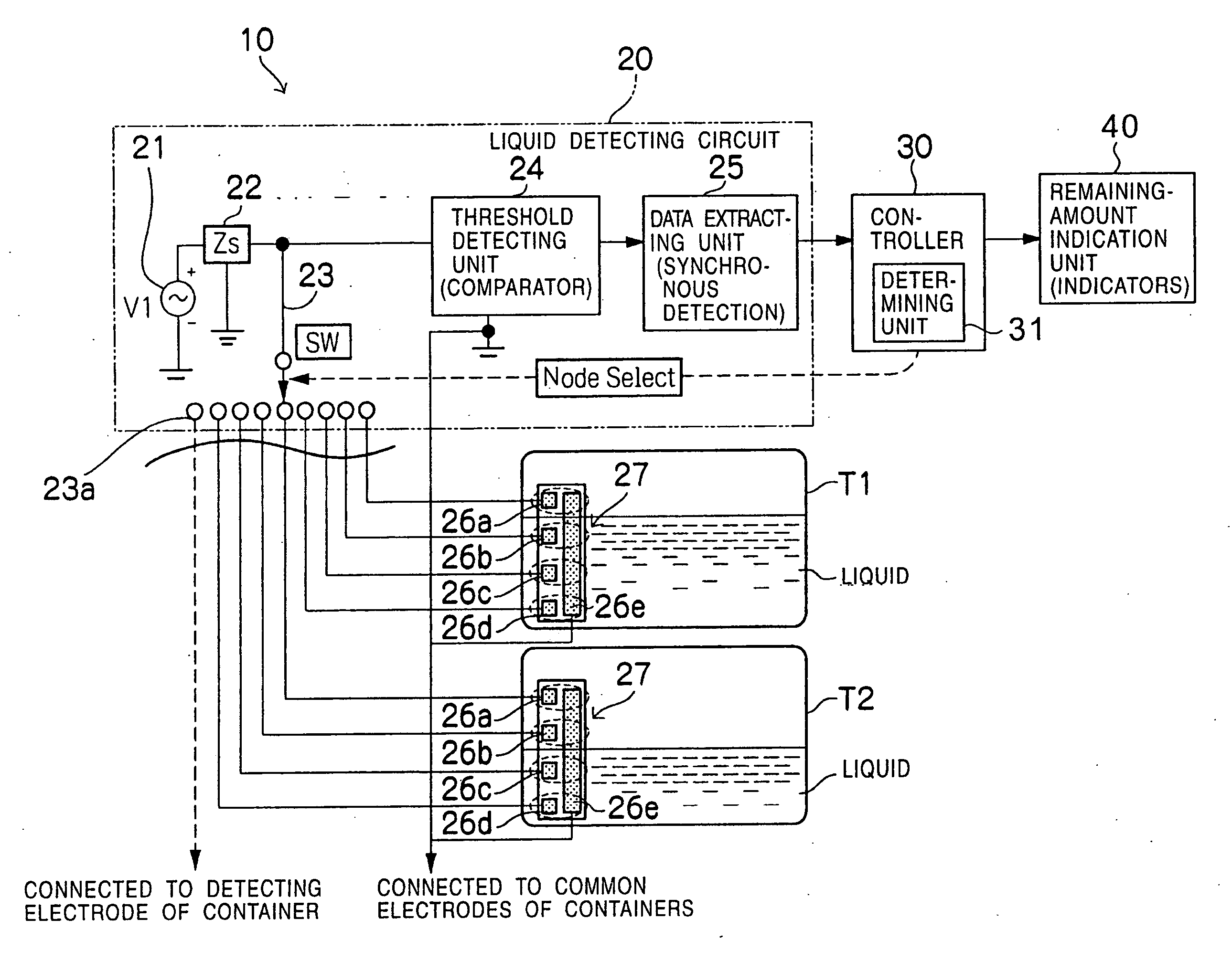
[0059]FIG. 4 is a diagram showing the construction of a liquid-amount detecting apparatus 10 according to a first embodiment of the present invention. As shown in FIG. 4, a conductive liquid that is to be detected by the liquid-amount detecting apparatus 10 is contained in containers T (T1 and T2).

[0060] For example, if the liquid-amount detecting apparatus 10 is used in an ink-jet printer, the containers T are ink tanks, and the liquid in the containers T is ink that is used in the ink-jet printer. In the case of a color ink-jet printer that uses ink of a plurality of colors, a container T (ink tank) is provided for each of the colors.

[0061] The liquid-amount detecting apparatus 10 according to this embodiment includes a liquid detecting circuit 20, a controller 30, and a remaining-amount indication unit 40.

[0062] The liquid detecting circuit 20 includes an AC-signal source (V1) 21, an impedance (Zs) 22, a switch (SW) 23, a. threshold detecting unit 24, a data extracting unit 25...

second embodiment

[0104]FIG. 7 is a waveform chart showing a second embodiment of the present invention, and it corresponds to FIG. 5 for the first embodiment.

[0105] In the first embodiment, the AC signal with a DC component having been removed therefrom is a rectangular wave; whereas in the second embodiment, a sine wave is used.

[0106] In FIG. 7, an original signal output from the AC-signal source 21 is a rectangular wave, as shown in part (A). This signal is converted, for example, through a low-pass filter, into a sine (or like) wave shown in part (B).

[0107] The signal shown in part (B) is obtained by converting a rectangular wave into a sine (or like) wave and removing a DC component from the sine wave. In part (A) of FIG. 7, as compared with part (A) of FIG. 5, the phase is shifted by ¼, as indicated by P5. Thus, the sine wave crosses 0 V at 1, 2, 3, . . . μsec.

[0108] Then, detection is performed when the clock signal rises (when the sine wave reaches a minimum level). The timing of detectio...

third embodiment

[0111]FIG. 8 is a circuit diagram showing a third embodiment of the present invention, and it corresponds to FIG. 6 for the first embodiment. FIG. 9 is a waveform chart relating to the circuit diagram shown in FIG. 8, and it corresponds to FIG. 5 for the first embodiment.

[0112] In the first embodiment, power sources of ±5 V are required, as shown in FIG. 6. In contrast, in the third embodiment, only a power source V2 of +5 V suffices to achieve the same functions as the first embodiment.

[0113] In this circuit, the average voltage of measurement equals the DC component of the clock signal. Thus, if a 5 V power source is used, measurement is performed at 2.5 V or nearly as a center. For the purpose of comparison, a DC power source V3 of 2.2 V, connected to the base of the transistor Q2, is used.

[0114] Furthermore, although all the nodes 23a of the switch 23 are connected to the detecting electrodes 26a to 26d in the first embodiment, a node 23a′ that is connected to the common elec...


PUM


Abstract

A liquid-amount detecting apparatus detects the amount of a liquid in containers. The liquid-amount detecting apparatus includes a liquid detecting circuit and a determining unit. The liquid detecting circuit includes electrode units disposed so as to be in contact with the liquid in the containers, which becomes electrically conductive when in contact with the liquid, an impedance, and an AC-signal source. An AC signal not containing a DC component is input from the AC-signal source to the electrode units through the source impedance, and a signal representing the status of electric connection of the electrode units is output. Furthermore, based on the output signal, a binary signal representing the presence or absence of electrical connection of the electrode units is output. The determining unit determines the presence or absence of the liquid at the electrode units based on the binary signal output from the liquid detecting circuit.

Description

BACKGROUND OF THE INVENTION [0001] 1. Field of the Invention [0002] The present invention relates to a liquid detecting apparatus or a liquid-amount detecting apparatus for detecting a liquid or the amount of a liquid in a container. For example, the present invention relates to an apparatus for detecting the remaining amount of ink in an ink tank of an ink-jet printer. [0003] 2. Description of the Related Art [0004] In an ink-jet printer, ink is stored in an ink tank, and the ink is transferred from the ink tank to an ink discharging unit (head) through an ink path, whereby droplets of ink is discharged. In the ink-jet printer, the presence or absence of ink must be detected with a relatively high precision. A first reason for this is that it is difficult to visually determine the remaining amount of ink from the external appearance of the ink tank. [0005] As a second reason, if the ink is discharged to such an extent that the ink is completely used up, ink that serves as “primer” ...

Claims


Application Information

Patent Timeline
Patent Type & Authority Applications(United States)
IPC IPC(8): B41J2/14B41J2/175B41J2/195G01F23/00G01F23/24G01F23/26G08B21/00
CPCB41J2/14427B41J2/17566G01F23/266G01F23/244G01F23/265G01F23/242B41J2/175
Inventor EGUCHI, TAKEOTAKENAKA, KAZUYASUNAMEKAWA, TAKUMI
Owner SONY CORP
Why Eureka
Try Eureka