
Total disc implant

a total disc and implant technology, applied in the field of total disc replacement implants, can solve the problems of preventing the progressive deterioration short-term relief, and almost certain degeneration of the patient's condition

Inactive Publication Date: 2005-10-27
AMEDICA A DELAWARE
View PDF99 Cites 93 Cited by
  • Summary
  • Abstract
  • Description
  • Claims
  • Application Information

AI Technical Summary

Benefits of technology

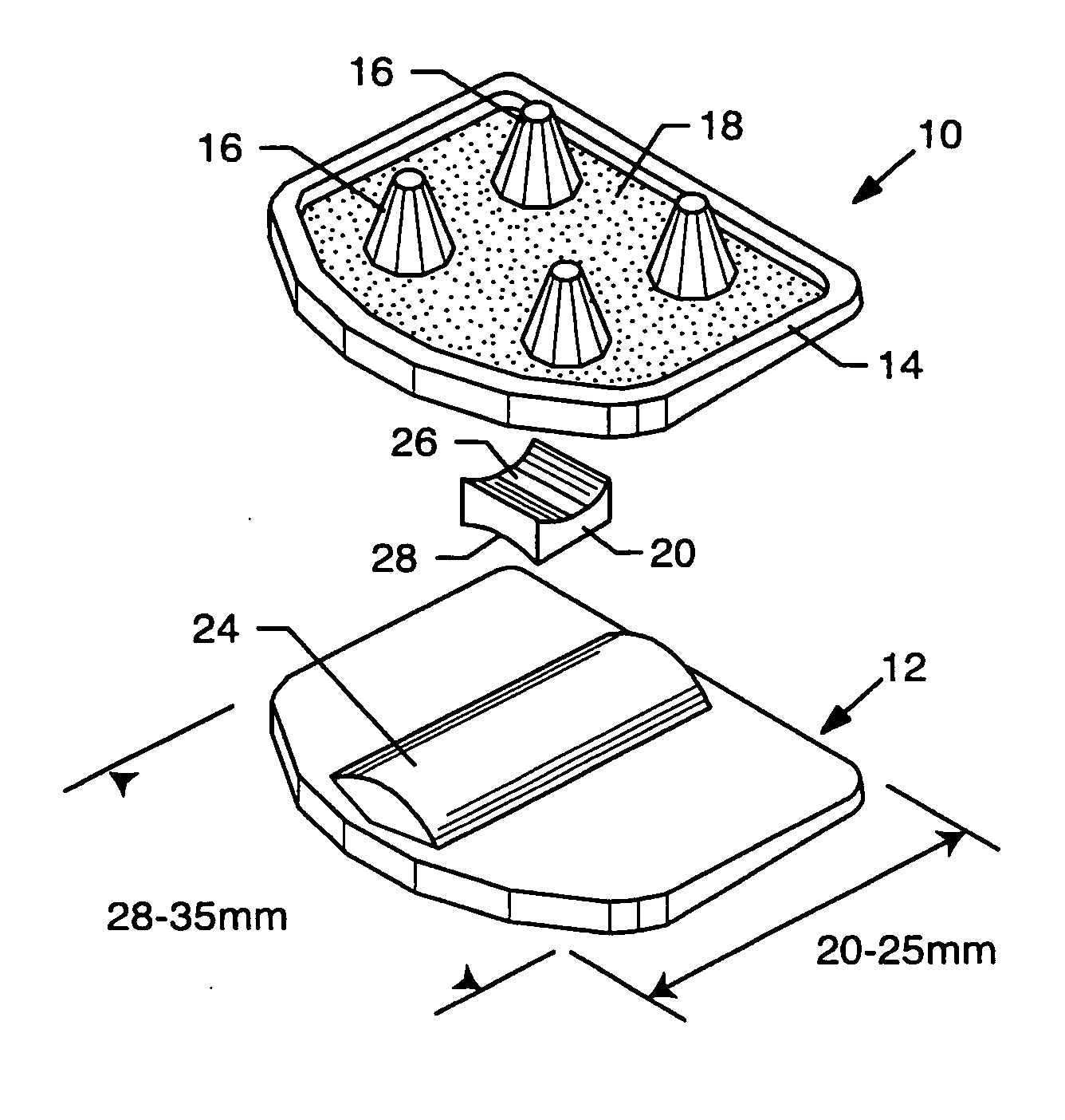
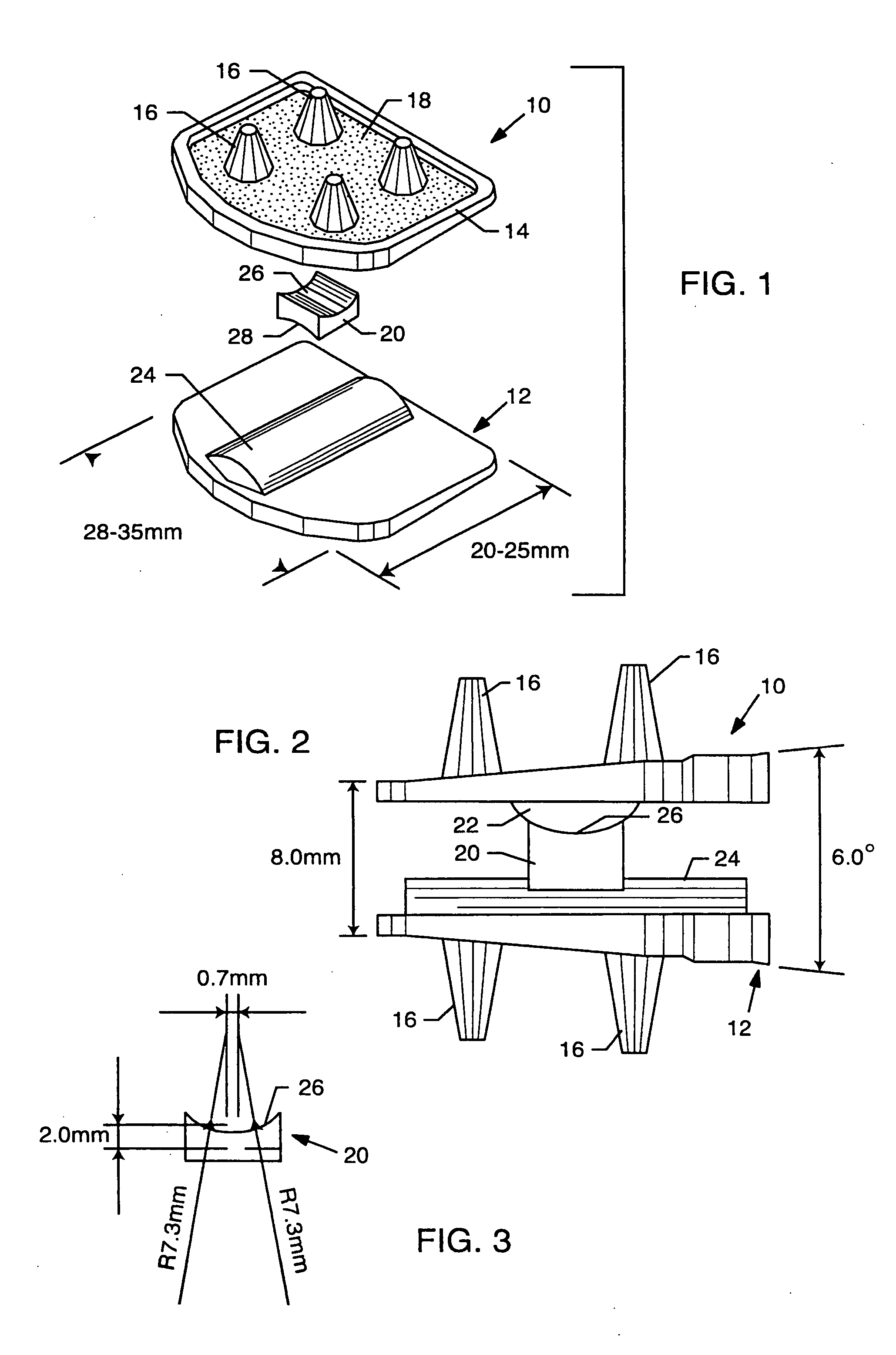
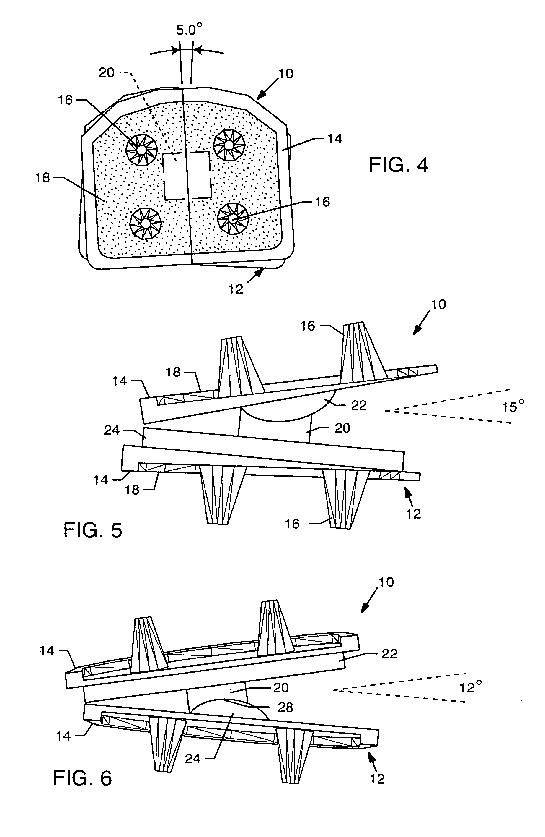
[0019] In one preferred form, the TDI generally comprises the upper and lower end plates for affixation to adjacent vertebral bodies, in combination with an intervening insert disposed therebetween. The upper and lower end plates include elongated and generally convex part-cylindrical surfaces oriented generally perpendicular to each other, with one of said surfaces extending in an anterior-posterior direction and other extending in a medial-lateral direction. The intervening insert defines concave upper and lower part-cylindrical seats oriented generally perpendicular to each other for respectively engaging these part-cylindrical surfaces, but wherein at least one and preferably both of these part-cylindrical seats are defined by offset radii to include a somewhat flattened central base region merging smoothly with upwardly curving radiused sides. With this geometry, the TDI accommodates a substantially full and natural range of motion, including anterior-posterior flexion, medial- lateral extension, and a limited range of axial rotation.
[0020] In an alternative form, an elongated and generally convex part-cylindrical surface is formed on one of the upper and lower end plates, and a generally convex part-cylindrical seat defined preferably by offset radii is formed on the other of the two end plates. When the upper and lower end plates are suitably affixed to adjacent vertebral bodies, the part-cylindrical convex surface is retained in articulating engagement with the part-cylindrical concave seat, in a manner permitting a substantially full and natural range of motion, including anterior-posterior flexion, medial-lateral extension, and a limited range of axial rotation.

Problems solved by technology

Statistics suggest that present surgical techniques are likely to result in short-term relief, but do not prevent the progressive deterioration of the patient's condition in the long run.
But it has become clear that unless the removed disc is replaced or the spine is otherwise properly supported, further degeneration of the patient's condition will almost certainly occur.
However, it has become increasingly apparent that unfused vertebral segments at the levels above and below the fused segment degenerate at accelerated rates as a direct result of this fusion.
None provide for a patient's return to near-normal functioning.
Though these procedures may address the symptoms in the short-term, they can result in progressive degeneration of discs at adjacent levels in the longer term.
The long history of similar metal / PE articulations for hip and knee protheses indicates that in the long term, PE wear particles are one of the principal causes of implant failures.
This wear debris is released into the peri-implant tissue and elicits a deleterious biologic reaction, incorporating foreign-body giant cell and macrophage cell responses leading to bone resorption, and eventual implant failure.
Early designs had unacceptable failures due to aseptic loosening resulting from poor conformity leading to instability, high contact stresses, and high PE insert wear.
Despite lower loads on the knee joint, backside wear of the PE tibial insert resulting from sliding motion was a major cause for concernv.
However new problems arise: bearings without stops can dislocate or spin-out, and bearings with stops can wear as they abut against the mechanical stops that prevent dislocation.viii
The present generation of total disc replacements use metal end plates which present problems with imaging MRI or in X-Ray -CT imaging, due to the presence of halos and other artifacts.

Method used


Image

  • Total disc implant
  • Total disc implant
  • Total disc implant

Examples


Embodiment Construction

[0045] The TDI design of the present invention is based on the principles of maintaining spine anatomy, restoring function by preserving segmental motion, providing immediate stability, withstanding spine loads safely, and providing rapid osteo-integration between implant / host bone.

[0046]FIGS. 1 and 2 show the proposed TDI design for lumbar spine. The design features an upper end plate 10 and a lower end plate 12 formed respectively with upper and lower surfaces that engage with the adjacent vertebral bodies (not shown). Each end plate 10, 12 includes a solid rim 14 substantially circumscribing the respective upper and lower surface to rest on the cortex of the adjacent vertebral body. Fixation elements such as fins, teeth or pins 16 protrude axially from the respective upper and lower surfaces of the end plates 10, 12 to provide anchoring and immediate stability with the adjacent vertebral bodies. These upper and lower surfaces include or are surface-coated each to define a porous...


PUM


Abstract

A total disc implant (TDI) is provided for total replacement of a spinal disc or discs in a human patient or other mammal, wherein the TDI is designed to maintain a substantially full range of natural motion (ROM) following implantation. The TDI generally comprises, in one preferred form, upper and lower end plates for affixation to adjacent vertebral bodies, with an intervening insert disposed therebetween. The end plates each include elongated part-cylindrical surfaces oriented generally perpendicular to each other, with one of said surfaces extending in an anterior-posterior direction and the other extending in a medial-lateral direction. The intervening insert defines concave upper and lower part-cylindrical seats oriented for respectively engaging these part-cylindrical surfaces, wherein these part-cylindrical seats are defined by offset radii to include a somewhat flattened central base region merging smoothly with upwardly curving radiused sides.

Description

BACKGROUND OF THE INVENTION [0001] This application claims the benefit of U.S. Provisional Application 60 / 434,092, filed Dec. 17, 2002. [0002] A novel motion preserving total disc replacement implant (TDI) is provided. The TDI is particularly designed for implantation into a human patient or other mammal, into the inter-vertebral space between adjacent spinal discs or vertebrae, as a prosthetic replacement for one or more surgically removed discs. The TDI beneficially provides a substantially full and natural post-operative range of motion (ROM). [0003] In the preferred form, the components of the TDI of the present invention are formed from ceramic materials, or biocompatible metals, or a combination thereof, with preferred ultra-low wear ceramic-ceramic or ceramic-metal articulatory components and materials being described in copending U.S. Ser. No. 10 / 171,376, filed Jun. 13, 2002, and entitled METAL-CERAMIC COMPOSITE ARTICULATION, which is incorporated by reference herein. Such u...

Claims


Application Information

Patent Timeline
IPC IPC(8): A61FA61F2/00A61F2/30A61F2/44
CPCA61F2/30767Y10S606/907A61F2002/30224A61F2002/30301A61F2002/30365A61F2002/30604A61F2002/30616A61F2002/30878A61F2002/30934A61F2002/443A61F2220/0033A61F2230/0069A61F2230/0095A61F2310/00023A61F2310/00029A61F2310/00317A61F2/4425
Inventor KHANDKAR, ASHOCK C.BRODKE, DARREL S.LAKSHMINARAYANAN, RAMASWAMY
Owner AMEDICA A DELAWARE
Learn More