
Method and apparatus for dispensing small volumes of fluid

a technology of fluid and small volume, applied in the direction of piston pumps, instruments, laboratory glassware, etc., can solve the problems of limited use of common solutions, limited use of precision metering equipment, and limited use of pumps, so as to achieve economic manufacture, maintain and operate

Inactive Publication Date: 2005-10-27
LEE COMPANY THE
View PDF17 Cites 6 Cited by
  • Summary
  • Abstract
  • Description
  • Claims
  • Application Information

AI Technical Summary

Benefits of technology

[0007] The method of the present invention consists of operating the system by reducing the pump chamber to a minimal volume and then with the inlet valve closed and the outlet valve open, a desired amount of buffer solution is drawn into the nozzle by increasing the chamber volume. Then the nozzle is placed in the fluid to be dispensed and a desired amount of that fluid is drawn into the nozzle by further increasing the chamber volume. If the initial volume of the chamber was filled with gas by expelling all fluid and opening the inlet valve, the next step may proceed with pressurization, and if not or if additional gas volume is desired, then next the outlet valve is closed and the inlet port is opened while the pump chamber volume is again further increased, thereby drawing gas into the pump chamber. Both valves are then closed and the pump chamber volume is decreased, thereby increasing the pressure within the chamber and compressing the gaseous volume in the chamber. Finally, a brief opening of the outlet valve then causes a determined amount of dispensate to be dispensed through the nozzle. Within a particular system, the volume dispensed is dependent on the pressurization of the gas within the pump and the length of time that the outlet valve is open. Systemic variations in performance can be readily achieved by modifying the nozzle configuration or buffer viscosity. While the system can be used to dispense larger volumes, it is anticipated that a primary advantage of the method is the ability to dispense extremely small volumes and for that purpose a relatively long nozzle is used with a small inside diameter.
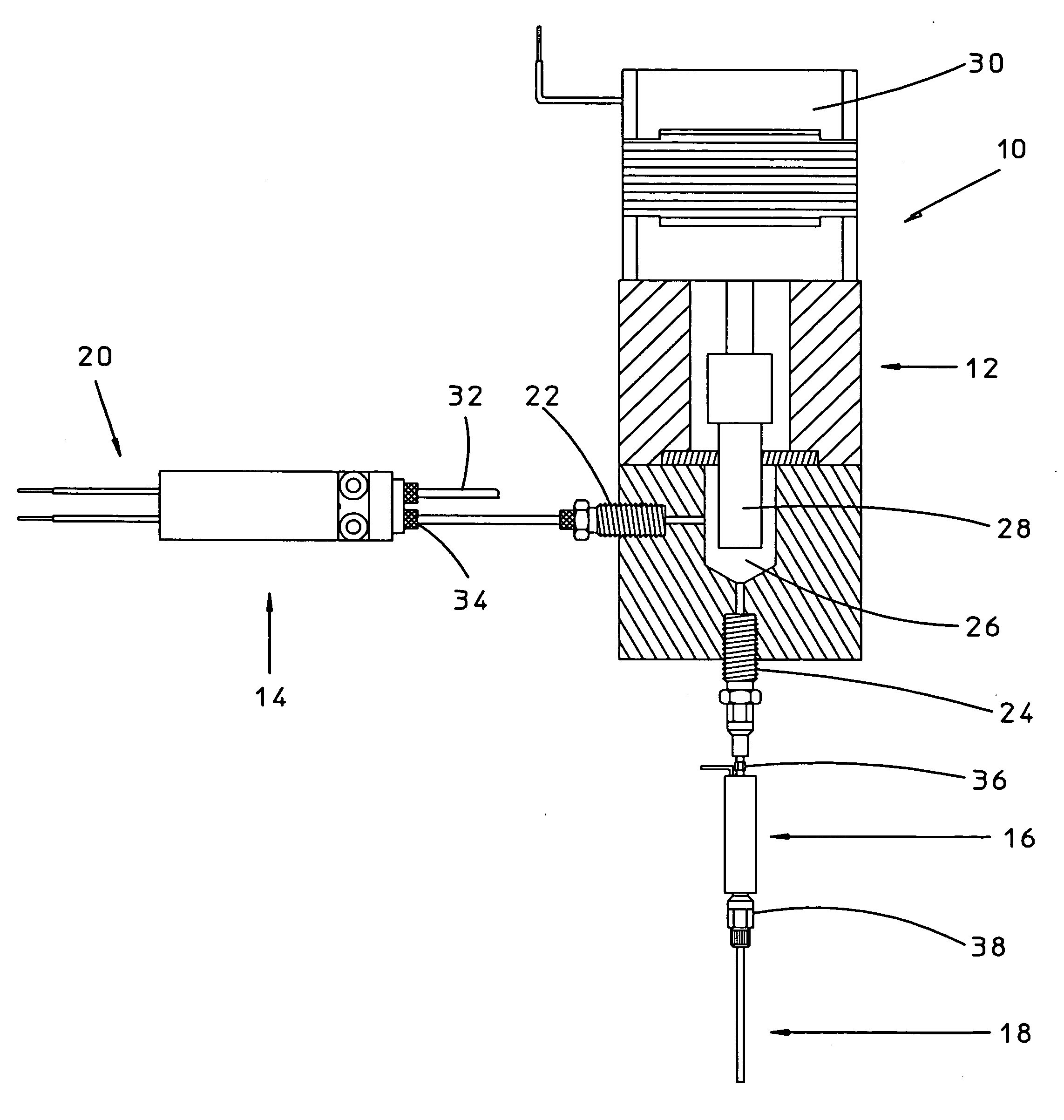
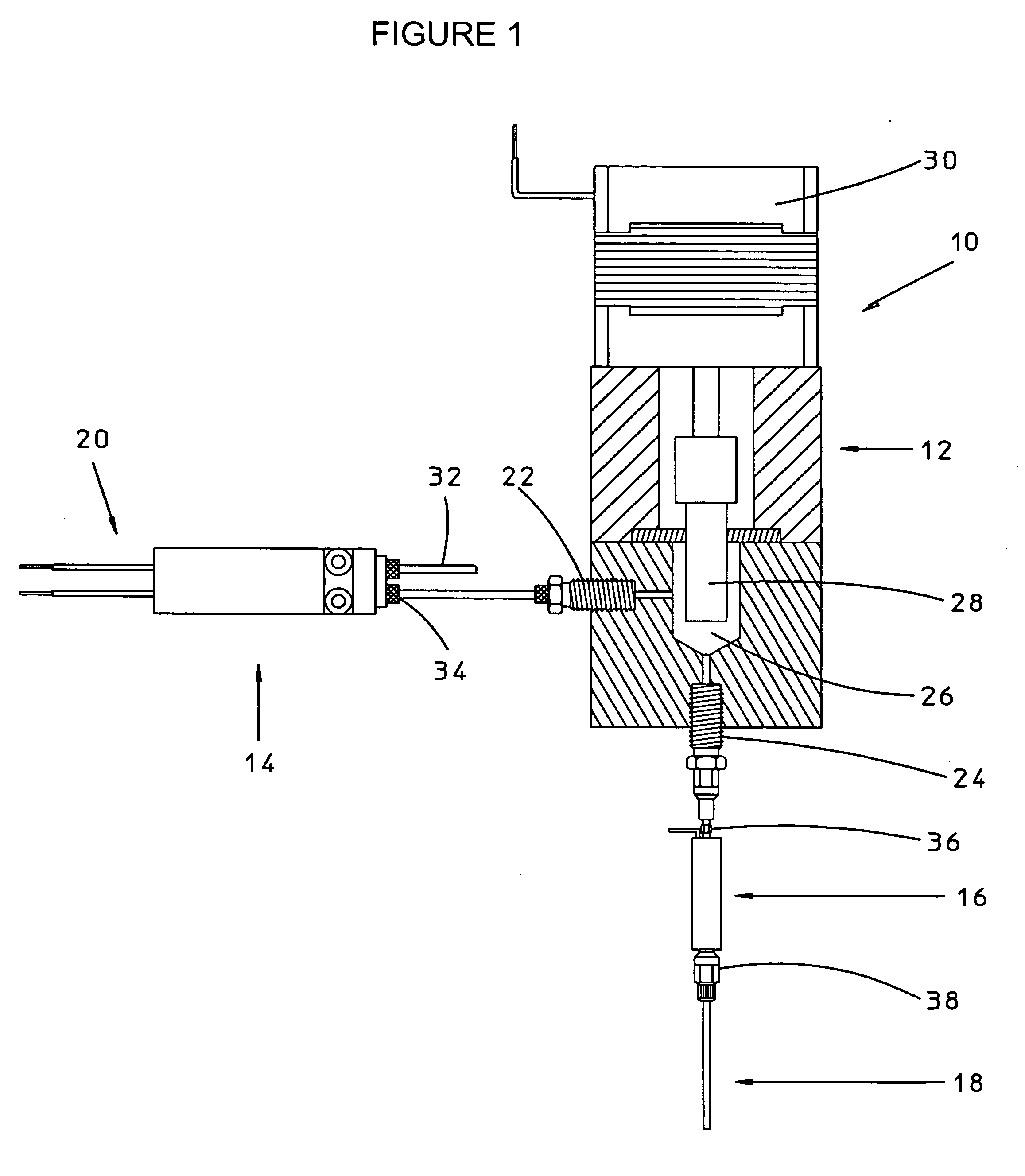
[0008] In the preferred embodiment, the outlet valve is a very high speed, solenoid actuated flow control valve and the nozzle is relatively long with a small inside diameter. A useful pump would be of the type using a volume displacing member actuated by a step drive to incrementally vary the internal volume of a pump chamber. In the specifically anticipated application of the present invention, with desired volumes of dispensate are droplets, small enough to be measured in the nanoliters. The volume of the droplets that can be dispensed may be smaller than could be accurately dispensed using the pump alone. It is further anticipated that the volume to be dispensed may be less than the interior volume of the nozzle, and accordingly, the dispensate would not be required to enter the outlet valve, thereby allowing a purging of the dispensate if desired and avoidance of contamination. Although it is anticipated that the use of a buffer solution provides many advantages, the system could be operated with only use of a fluid to be dispensed, if enough is drawn into the system to allow proper functioning of the outlet valve.
[0012] Another and further object and aim of the present invention is to provide a new and improved fluid dispensing system that meets the foregoing requirements and which is economical to manufacture, maintain and operate.

Problems solved by technology

In systems requiring a means of dispensing extremely small amounts of fluid, limitations of size, external plumbing, and economics of precision metering equipment limit the usefulness of common solutions.
For example, direct use of a simple dispensing pump to push a small volume out a nozzle requires the pump to perform a very limited operation.
In many applications in which such small volumes of fluid are desired, the allowable margin of error may be difficult to achieve due to normal pump operation variances.
In some applications however, supplying pneumatic pressure to an array of nozzles can be cumbersome and may not allow use in applications where space is limited.

Method used


Image

  • Method and apparatus for dispensing small volumes of fluid
  • Method and apparatus for dispensing small volumes of fluid

Examples


Embodiment Construction

)

[0016] With reference to the Drawing wherein like numerals represent like parts, a dispensing system constructed in accordance with the method of the present invention is generally designated by numeral 10 in FIG. 1. The method of the present invention comprises assembling and operating dispensing system 10 comprising a pneumatic intake valve 14, a variable volume pump 12, a fast acting flow control valve 16 and a nozzle 18. Variable volume pump 12 comprises an inlet port 22, an outlet port 24, a pump chamber 26 and a means for controllably altering the volume of pump chamber 26 in discrete increments, which in the illustrated preferred embodiment consists of a piston 28. It will be noted that although pump 12 is describes as such herein, pump 12 departs from normal pump configuration by the lack of one directional valving, such as a check valve at the outlet port; pump 12 having only a variable chamber 26. In the preferred embodiment, outlet valve 16 is a very high speed, solenoid...


PUM


Abstract

A method and apparatus for dispensing small volumes of fluid using a pneumatic control valve connected to the intake port of a pump having a chamber of variable volume, connecting the outlet port of the pump to the inlet port of a high speed flow control valve and a long, small diameter nozzle to the outlet port of the flow control valve, to aspirate a fluid to be dispensed into a long, small diameter nozzle by closing the pneumatic control valve, opening the flow control valve and partially expanding the volume of the pump chamber, then closing the flow control valve and further expanding the volume of the pump chamber to increase the gaseous volume within the pump chamber, pressurizing the gas within the pump chamber by closing the pneumatic control valve and reducing the volume of the pump chamber, finally dispensing a measured amount of fluid by briefly opening the flow control valve for a measured time to allow controlled amounts of fluid to be dispensed through the nozzle.

Description

CROSS REFERENCE TO RELATED PROVISIONAL APPLICATION [0001] This application claims the benefit of U.S. Provisional Application No. 60 / 467,991, filed May 5, 2003.BACKGROUND OF THE INVENTION [0002] A. Field of Invention [0003] The present invention relates generally to methods and apparatus for dispensing small volumes of fluid and more particularly to a new and improved method of dispensing very small volumes of fluid by means of an apparatus comprised of known and available fluid control components in a novel arrangement. [0004] B. Description of Related Art [0005] In systems requiring a means of dispensing extremely small amounts of fluid, limitations of size, external plumbing, and economics of precision metering equipment limit the usefulness of common solutions. For example, direct use of a simple dispensing pump to push a small volume out a nozzle requires the pump to perform a very limited operation. For example, a simple displacement pump must operate either an extremely small...

Claims


Application Information

Patent Timeline
IPC IPC(8): B67D1/00F04B1/00F04B7/00F04B13/00F04B17/00F04F1/06G01F11/02G01F13/00
CPCB67D1/1277F04B7/0076G01F13/006F04F1/06G01F11/021F04B13/00
Inventor NADEL, ARTHUR
Owner LEE COMPANY THE
Learn More