
Wheelchair locking device

Inactive Publication Date: 2005-10-27
LEMAY CHRISTIAN
View PDF19 Cites 11 Cited by
  • Summary
  • Abstract
  • Description
  • Claims
  • Application Information

AI Technical Summary

Benefits of technology

[0010] The present invention reduces the difficulties and disadvantages of the aforesaid designs by providing a locking device, which is housed in a cylindrical housing. The cylindrical housing advantageously significantly reduces or essentially eliminates the aforesaid problems of inefficient space use due to excessive bulk. Moreover, the shape of the housing permits the wheelchair user free, unrestricted maneuverability about the housing during initial embarking in a vehicle. The locking device is mounted within the housing and is hidden from view so that danger from catching clothing and the like is significantly reduced. Moreover, the locking device securely holds a wheelchair locking pin using a novel mating assembly of plates which are resiliently biased into engagement. A retaining barrier ensures that the locking pin is held firmly between the mated plates. The locking device may be released using either a simple mechanical or electrical operation. The housing with the locking device may be retrofitted into an existing vehicle without the need for extensive modification to either the wheelchair or to the vehicle. Furthermore, the locking device is easy to operate and inexpensive to install.

Problems solved by technology

Transporting wheelchair-bound individuals is an on-going challenge, especially since the wheelchairs are bulky and awkward to maneuver in confined spaces such as within an interior of a vehicle.
Once the wheelchair is located in the vehicle, another challenge is to stabilize the wheelchair to reduce its movement during transportation.
However, the aforesaid designs suffer from a number of significant disadvantages.
The housings for most of the designs are bulky and do not appear to permit easy maneuvering of the wheelchair within the vehicle.
The locking devices used in the housings are complex and may require extensive modification to either the wheelchair or the vehicle.
This may be prohibitively expensive, which may decrease the accessibility of the designs to most users.
In addition, some of the locking devices have exposed guide mechanisms, which may trap dirt requiring regular cleaning and maintenance.
Moreover, the exposed mechanisms may pose danger from trapping articles of clothing or body parts.

Method used


Image

  • Wheelchair locking device
  • Wheelchair locking device
  • Wheelchair locking device

Examples


Embodiment Construction

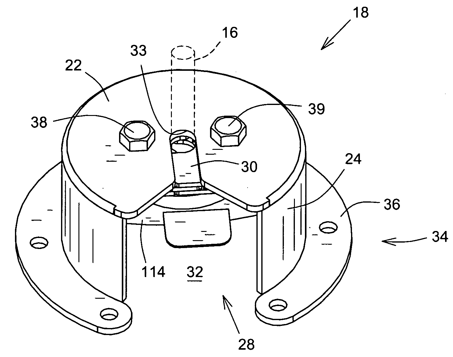
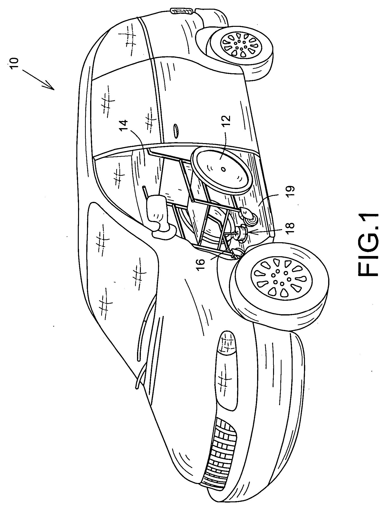
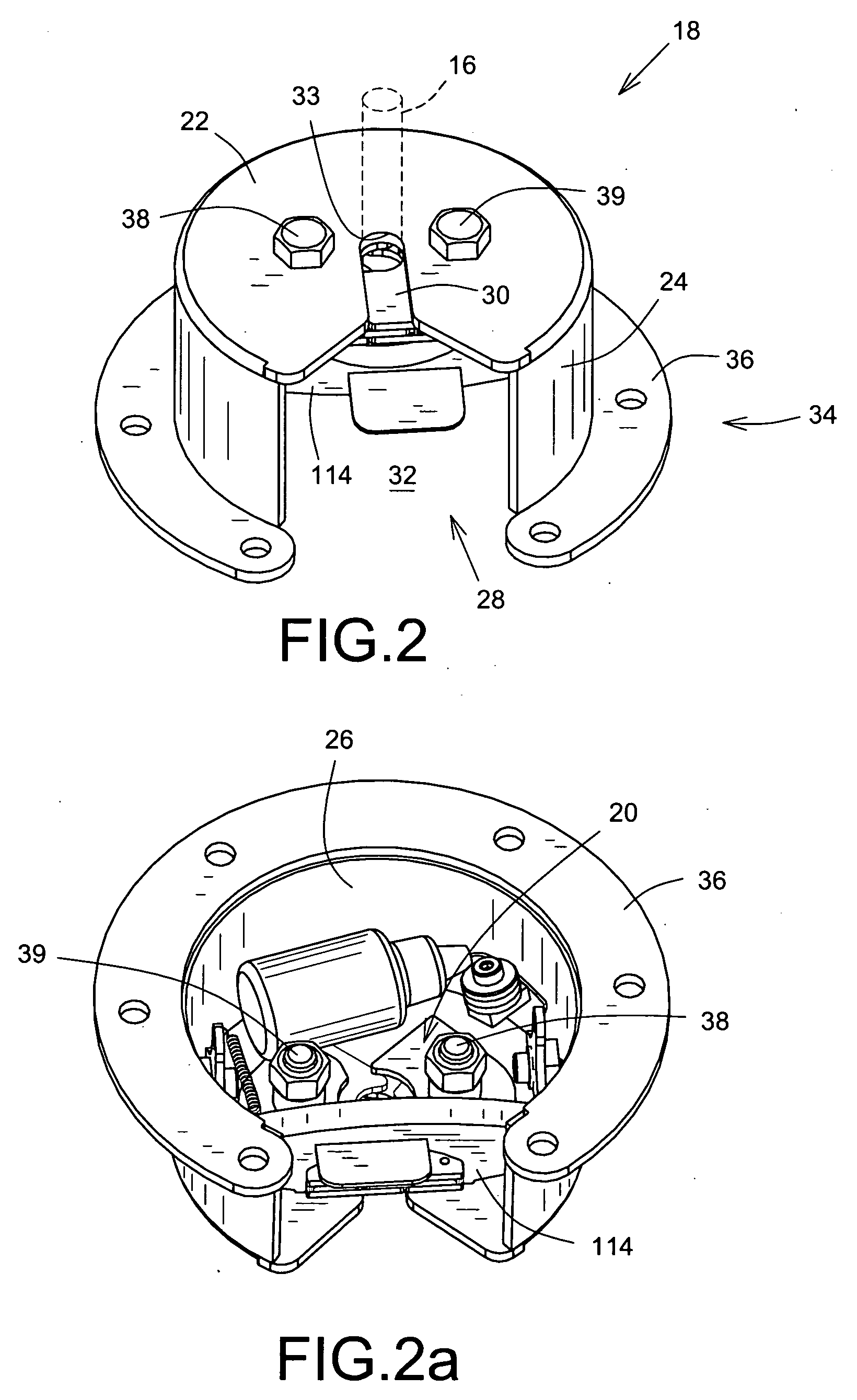
[0023] Referring to FIGS. 1 to 3, a vehicle, such as a minivan and the like, is shown generally at 10. The vehicle 10 is typically adapted to permit access of a wheelchair 12 into an interior 14 of the vehicle 10. The wheelchair 12 includes a downwardly depending locking pin 16 connected to the wheelchair frame and is typically an elongate shaft with a nut connected to an end furthest away from the wheelchair frame. A housing apparatus 18 is connected to a floor 19 of the vehicle 10 and houses a locking device 20 for mounting and retaining the wheelchair 12 in the vehicle 10. The housing 18 is located in the interior 14 of the vehicle 10 and includes a top wall 22 and a sidewall 24. The top wall 22 and the sidewall 24 define an inner chamber 26 for mounting the locking device 20 therein. The sidewall 24 and the top wall 22 are shaped to permit the wheelchair 12 unrestricted rotation thereabout at a time when the locking pin 16 is engaging the locking device 20, such as when a user f...


PUM


Abstract

A locking device for mounting a wheelchair in a vehicle, in which the wheelchair has a downwardly depending locking pin. The device includes two plate members and a connecting portion, which connects the plate members. The plate members are movable with respect to each other about the connecting portion and mate together to retain the locking pin between the plate members.

Description

FIELD OF THE INVENTION [0001] The present invention concerns locks and more particularly to locks to stabilize wheelchairs in a vehicle. BACKGROUND OF THE INVENTION [0002] Transporting wheelchair-bound individuals is an on-going challenge, especially since the wheelchairs are bulky and awkward to maneuver in confined spaces such as within an interior of a vehicle. Once the wheelchair is located in the vehicle, another challenge is to stabilize the wheelchair to reduce its movement during transportation. To aid locking, the wheelchairs often have to be adapted such as by connecting a downwardly depending locking pin to a lower part of the wheelchair's frame. The locking pin is guided into a lock housing mounted on the vehicle's floor and which retains the pin and therefore the wheelchair. A number of designs exist which address the aforesaid challenges, a few examples of which are: [0003] U.S. Pat. No. 4,062,209, issued Dec. 13, 1977 to Downing et al., for “Wheelchair Lock”; [0004] U...

Claims


Application Information

Patent Timeline
IPC IPC(8): A61G3/08B60P3/06
CPCA61G3/0808A61G2220/145
Inventor LEMAY, CHRISTIAN
Owner LEMAY CHRISTIAN
Learn More