
Power wheelchair

a wheelchair and power technology, applied in the field of wheelchairs, can solve the problems of inability to achieve, the occupant cannot clearly see in the direction of the wheelchair, etc., and achieve the effect of avoiding the occurrence of tipping and tilting and avoiding impact with obstacles

Inactive Publication Date: 2005-10-27
SUNRISE MEDICAL HHC INC
View PDF20 Cites 118 Cited by
  • Summary
  • Abstract
  • Description
  • Claims
  • Application Information

AI Technical Summary

Benefits of technology

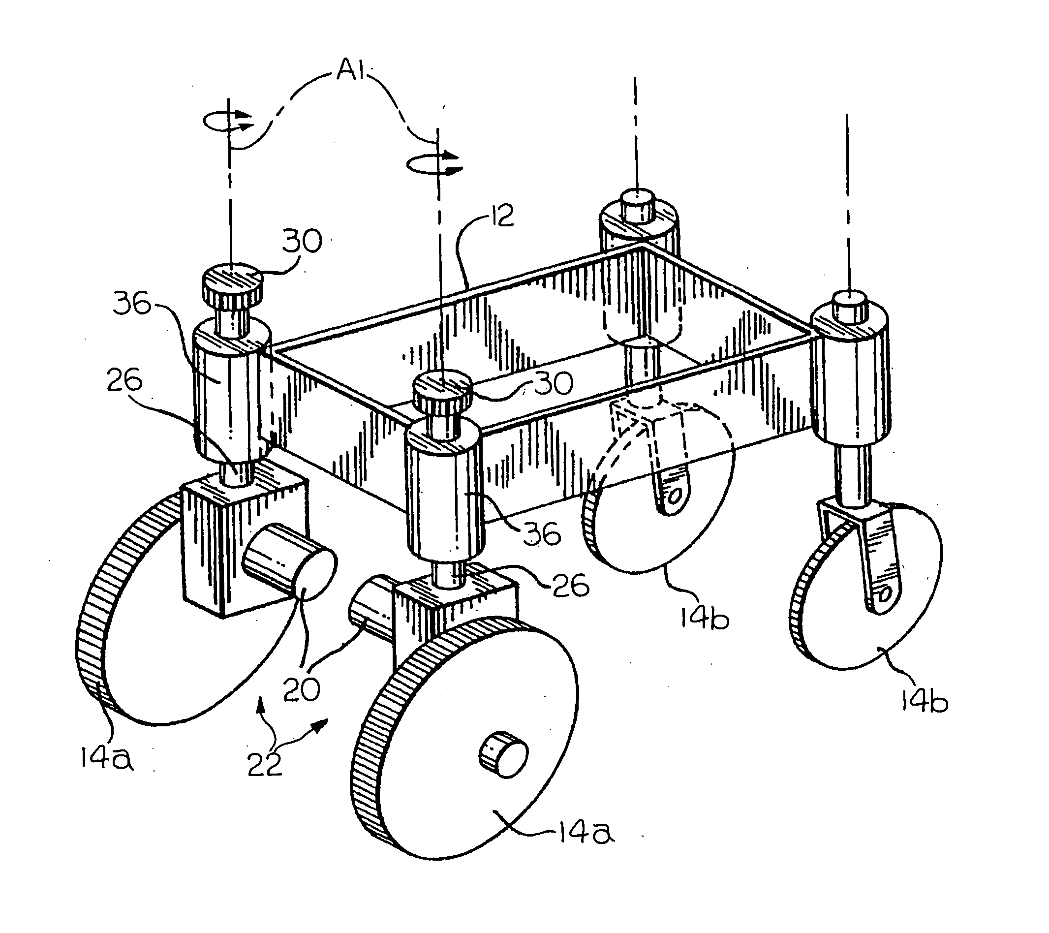
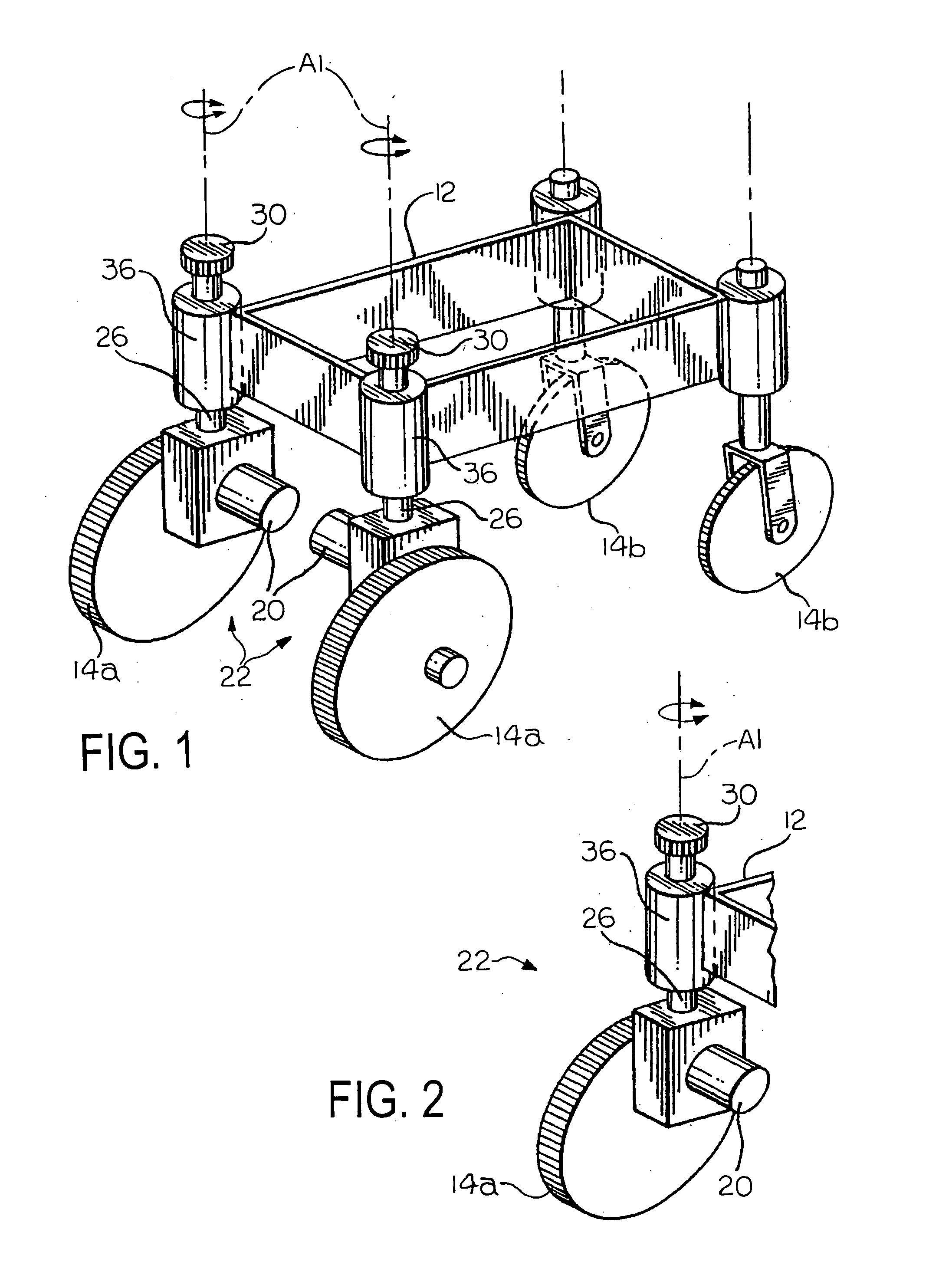
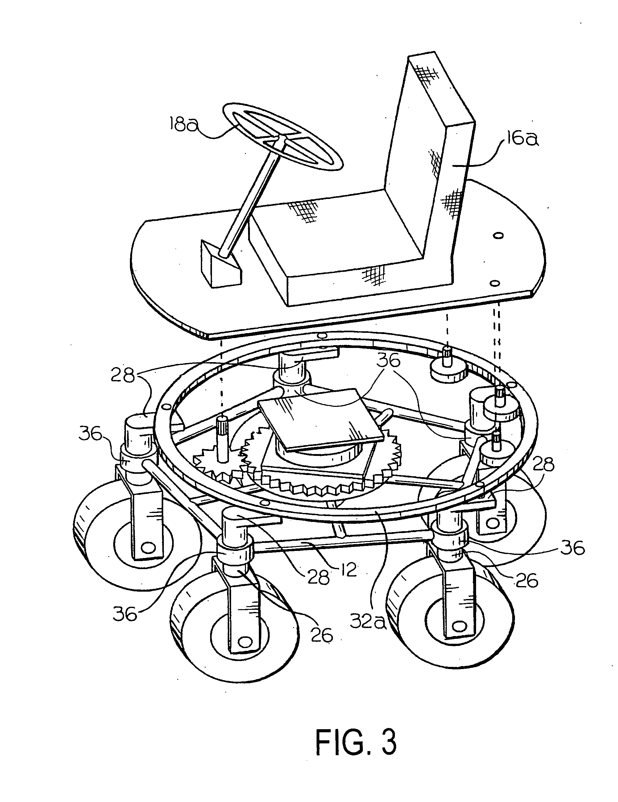
[0007] The present invention is directed toward a wheelchair having a base and a plurality of wheels supporting the base on a supporting surface. At least one of the wheels is a driven wheel. One of the wheels may be a non-driven wheel. One or more of the wheels, driven or non-driven, is adapted to be steered. In a preferred embodiment of the invention, all of the wheels are driven and steered independently of one another. The wheelchair also has a seat that is mounted for movement relative to the base. Movement of the seat is preferably controlled independently of the steering direction of the wheels. The wheelchair may further include one or more sensors for controlling the stability of the wheelchair. These sensors may include wheel position sensors, speed sensors, rate-of-turn sensors, accelerometers, and proximity detectors. Such sensors would be useful in controlling the tracking of the wheelchair, avoiding the occurrence of tipping and tilting, and avoiding impact with obstacles.

Problems solved by technology

One disadvantage to this arrangement is that, if one of the wheelchair wheels becomes misaligned, then that wheel must be disconnected from the steering and once again arranged in parallel with the other wheels.
One disadvantage to this advancement is that the seat is always linked to the steering linkage and thus always moves in response to the wheelchair wheels.
This cannot be achieved if the seat is linked to the steering linkage.
Moreover, the seat does not track the position of the wheelchair wheels.
Moreover, the orientation of the seat relative to the direction of travel of the wheelchair may position the wheelchair occupant, who often has little manual dexterity, so that the occupant cannot clearly see in the direction that the wheelchair is traveling.

Method used


Image

  • Power wheelchair
  • Power wheelchair
  • Power wheelchair

Examples


Embodiment Construction

[0017] Referring now to the drawings, there is illustrated in FIG. 1 a chassis or base 12, which is supported for movement relative to a supporting surface (i.e., the ground or a floor) by a plurality of wheels 14a, 14b. A body or seat 16a, 16b (illustrated in FIGS. 3-5) is adapted to be supported relative to the base 12. The seat 16a, 16b is provided for supporting an occupant (not shown). The base 12 is adapted for use in a wheelchair, which may be controlled by the occupant via an operator interface or input device 18a, 18b (illustrated in FIGS. 3-5). The input device 18a, 18b may be, for example, in the form of a steering wheel, a joystick, a sip and puff control, or a head-movement device.

[0018] According to the preferred embodiment of the invention, the wheelchair is a power wheelchair, wherein one or more of the wheels 14a are driven (i.e., rotated about a horizontal axis) by a motor. The driven wheels 14a may be driven collectively by a single motor and a mechanical drive c...


PUM


Abstract

A wheelchair has a base and a plurality of wheels supporting the base on a supporting surface. At least one of the wheels is a driven wheel. One of the wheels may be a non-driven wheel. One or more of the wheels, driven or non-driven, is adapted to be steered. In a preferred embodiment of the invention, all of the wheels are driven and steered independently of one another. The wheelchair also has a seat that is mounted for movement relative to the base. Movement of the seat is preferably controlled independently of the steering direction of the wheels. The wheelchair may further include one or more sensors for controlling the stability of the wheelchair. These sensors may include wheel position sensors, speed sensors, rate-of-turn sensors, accelerometers, and proximity detectors. Such sensors would be useful in controlling the tracking of the wheelchair, avoiding the occurrence of tipping and tilting, and avoiding impact with obstacles.

Description

CROSS REFERENCE TO RELATED APPLICATIONS [0001] This application claims the benefit of U.S. Provisional Patent Application No. 60 / 565,607, filed on Apr. 27, 2004.BACKGROUND OF INVENTION [0002] This invention relates in general to wheelchairs and more particularly to wheelchair steering and stability controls. [0003] Recent advancements in wheelchairs have led to greater steering capability and more stable control of the wheelchair. One advancement, for example, has been in the area of steering controls, wherein all of the wheelchair wheels are collectively steered by a common steering linkage. In this arrangement, all of the wheelchair wheels are arranged in parallel and then connected to the steering linkage. One disadvantage to this arrangement is that, if one of the wheelchair wheels becomes misaligned, then that wheel must be disconnected from the steering and once again arranged in parallel with the other wheels. [0004] Another advancement in steering has been with regard to lin...

Claims


Application Information

Patent Timeline
IPC IPC(8): A61G5/04A61G5/10A61G7/05B60K7/00B60K17/30B60L15/20B62D7/00B62D7/02B62D7/15
CPCA61G5/045A61G2203/36A61G2005/1051A61G2007/0528A61G2203/14B60K7/0007B60K17/043B60K17/303B60K2007/0046B60K2007/0061B60L2220/46B60Y2200/84B62D7/026B62D7/1509Y02T10/7258A61G5/1072A61G5/1051A61G7/0528Y02T10/72
Inventor RUNKLES, RICHARDKOERLIN, JAMES
Owner SUNRISE MEDICAL HHC INC
Learn More