
Warhead with integral, direct-manufactured features

a direct-manufactured, integrated technology, applied in the direction of additive manufacturing apparatus, weapons, ammunition projectiles, etc., can solve the problems of reducing design options, limiting the number of parts, reducing touch labor, design/development/production costs, etc., to facilitate steering performance, optimize fragmentation, and optimize penetration

Inactive Publication Date: 2005-10-27
LOCKHEED MARTIN CORP
View PDF3 Cites 55 Cited by
  • Summary
  • Abstract
  • Description
  • Claims
  • Application Information

AI Technical Summary

Benefits of technology

The patent describes a method for creating customizable warheads using direct manufacturing techniques. These techniques allow for the rapid and flexible design of warheads, allowing for the use of non-homogeneous materials and construction approaches. This method also reduces the need for touch labor and increases the ability to tailor warhead performance to specific application requirements. Overall, the patent provides a faster and more flexible way to develop and manufacture warheads, leading to increased innovation and productivity.

Problems solved by technology

The technical problem addressed in this patent text is the limitations of conventional warhead manufacturing methods in terms of shape, size, material composition, and capabilities, as well as the increased design and fabrication costs and reduced design options caused by multiple part subassembly constructions. The text also highlights the hindrance of design and fabrication cycles caused by the need for design and fabrication of molds and other overhead equipment. The patent aims to provide a solution to these problems by introducing a new method for manufacturing warheads that allows for more efficient and cost-effective design options and rapid prototyping activities.

Method used


Image

  • Warhead with integral, direct-manufactured features
  • Warhead with integral, direct-manufactured features
  • Warhead with integral, direct-manufactured features

Examples


Embodiment Construction

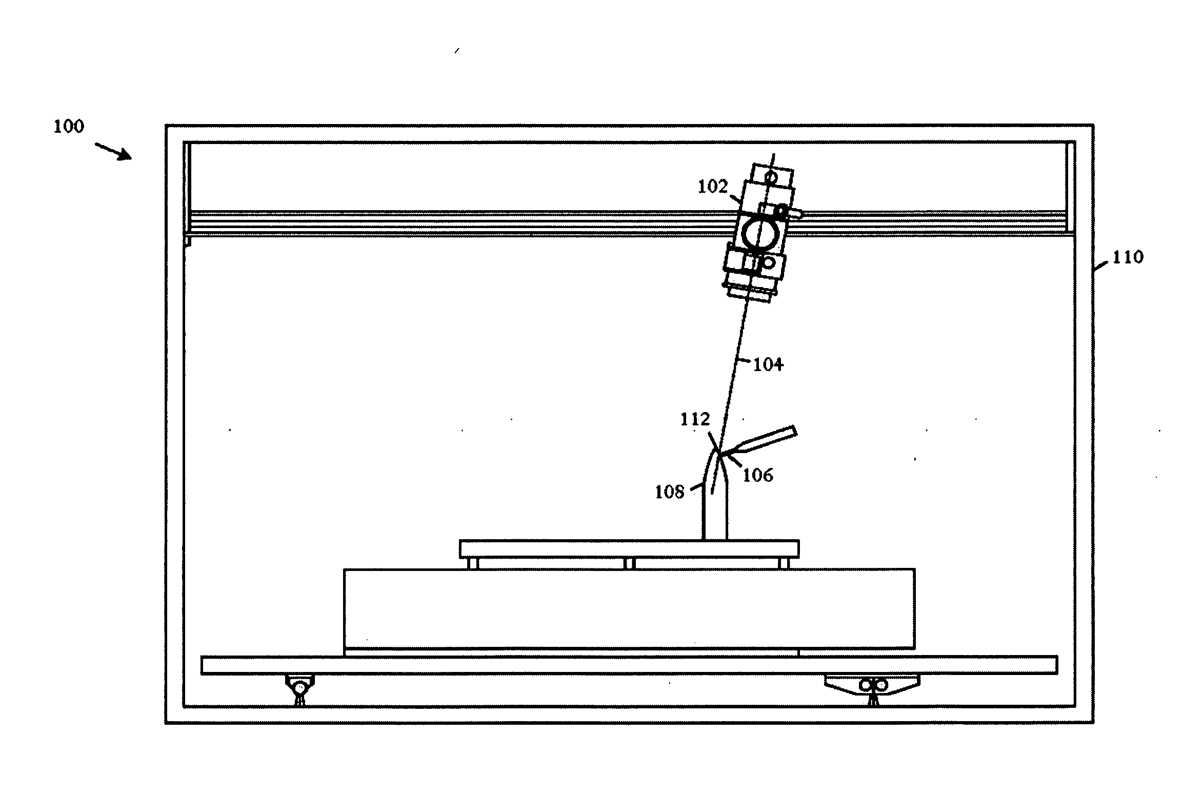
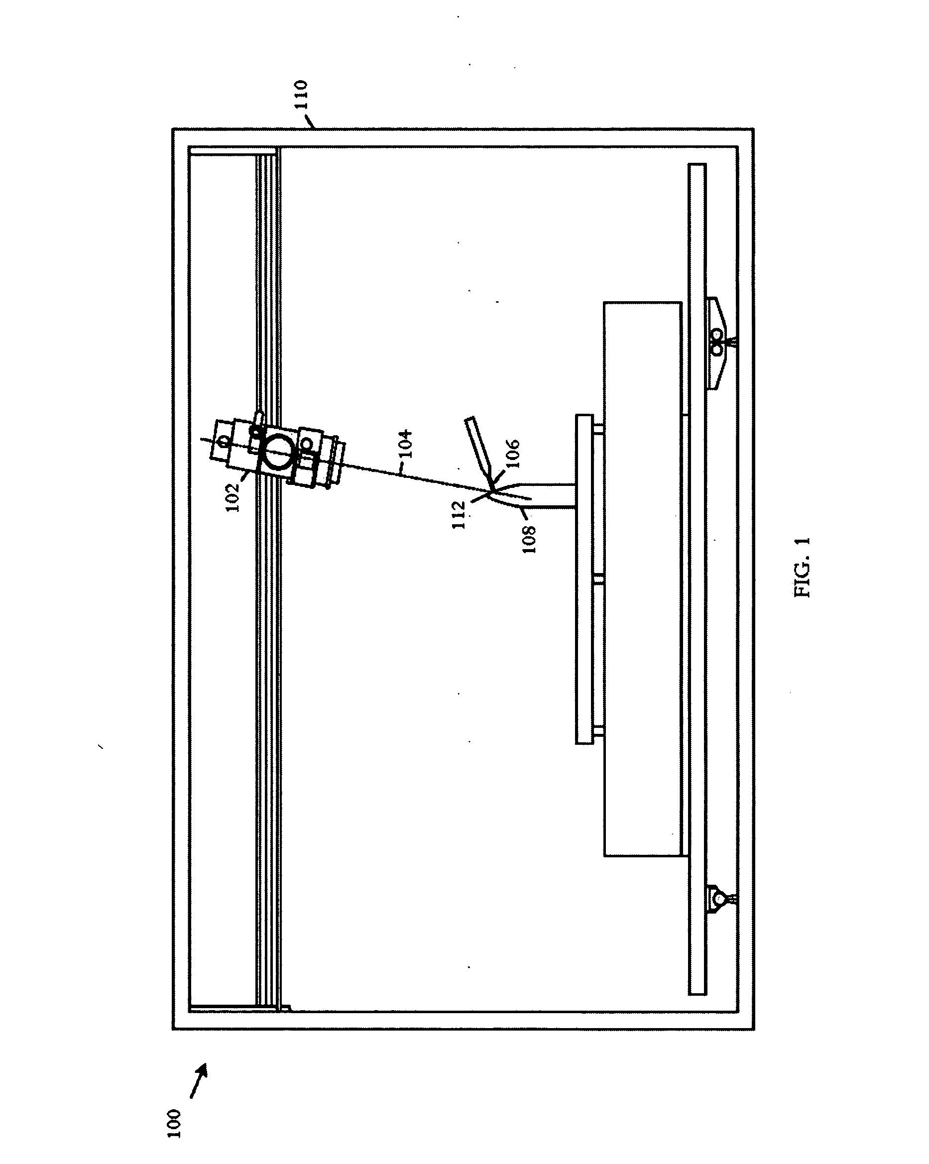
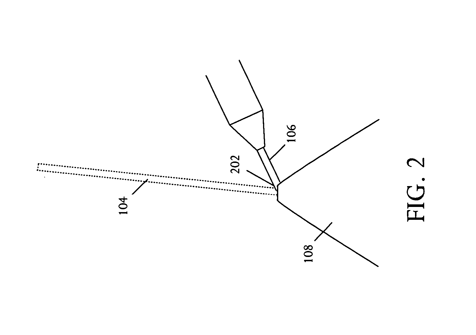
[0030] Referring to FIG. 1, a schematic pictorial diagram illustrates an example of a suitable high energy density direct manufacturing device 100 for use in fabricating warheads and warhead structures. The illustrative high energy density direct manufacturing device 100 is a precision controlled moving-gun electron beam welding system although other devices can also be used, for example laser beam devices, plasma arc deposition devices, and others. The direct manufacturing process or method is similar to welding using a high energy heat source to create a molten pool on a substrate and adding wire or powder material to the molten pool to create a deposited bead of material. These deposited beads can be combined to create a layer of deposited material, and many layers can be combined to create a large deposited structure.

[0031] The direct manufacturing device 100 includes an electron beam gun 102 that produces an energy beam 104, illustratively an electron beam, used to melt the su...


PUM


Abstract

Warhead structures and features are fabricated using direct manufacturing technologies, a method for fabricating bulk warhead structures by sequential and additive deposition of melted feedstock layers. Suitable energy sources for melting the feedstock can be various high energy density technologies including laser, electron beam, plasma arc deposition, and the like. The high energy density in combination with high cooling rates results in structures with homogeneous microstructures. The feedstock can be in the form of wire or powder and is applied to a substrate by introduction to a molten pool on the substrate, accumulating to additively combine with the substrate. The approach provides for warhead structures with singular and combined unique features to include: integral constructions, tailored fragmentation patterns, use of dissimilar materials for special effects, and variable material property constructions for enhanced performance.

Description


Claims


Application Information

Patent Timeline
Owner LOCKHEED MARTIN CORP
Learn More