
Power transmission device

a transmission device and power technology, applied in the direction of shock absorbers, fluid couplings, hoisting equipments, etc., can solve the problem of excessive shock on the transmission member, and achieve the effect of reliably preventing collision nois

Active Publication Date: 2005-10-20
SANDEN CORP
View PDF3 Cites 9 Cited by
  • Summary
  • Abstract
  • Description
  • Claims
  • Application Information

AI Technical Summary

Benefits of technology

The invention is a power transmission device that reduces vibration and noise during rotation. It achieves this by using a shock absorbing rubber placed between protrusions on the drive and driven rotors. An elastic member is also placed between the shock absorbing rubber and the protrusions to absorb any sudden rotation number changes caused by rattling. This prevents vibration and collision noise during rotation.

Problems solved by technology

Thus, in the case where power is transmitted from a drive source such as an automobile engine where periodical rotation number changes occur, the clearance may cause vibration in a rotation direction or collision noise, or an inertial force of the transmission member in a rotation area that is not subjected to shock absorbing action of the shock absorbing rubber may cause an excessive shock on the transmission member at the time of an abrupt rotation number change.

Method used


Image

  • Power transmission device
  • Power transmission device
  • Power transmission device

Examples


Embodiment Construction

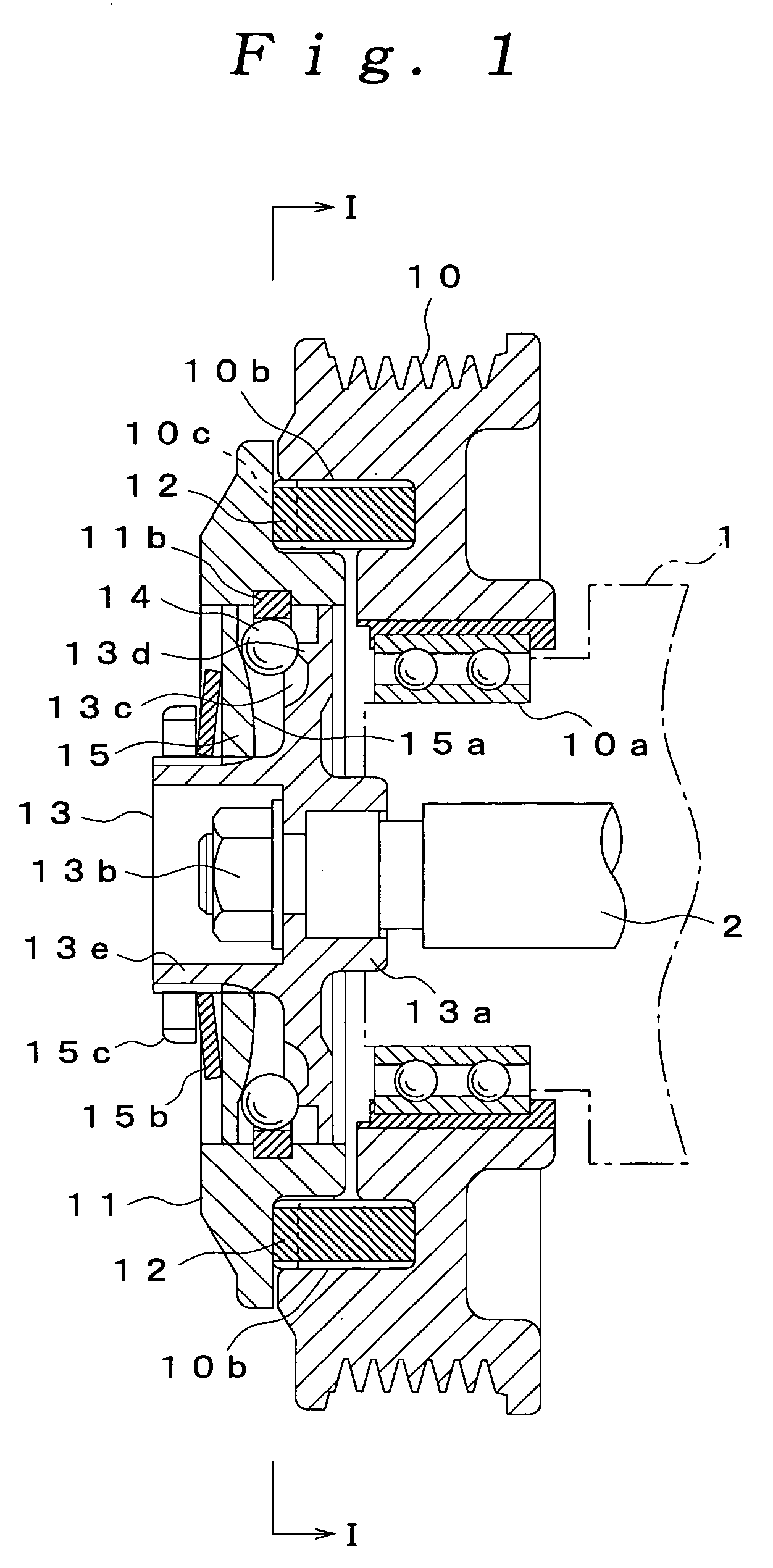
[0018] FIGS. 1 to 7 show an embodiment of the invention, and a power transmission device in FIGS. 1 to 7 is used in a compressor in a vehicle air conditioning device, and transmits power to a drive shaft 2 protruding from one end of a compressor body 1.

[0019] The power transmission device according to the embodiment includes a pulley 10 as a drive rotor rotated by external power, a transmission ring 11 as a driven rotor rotated by the pulley 10, a plurality of shock absorbing rubbers 12 that transmit torque of the pulley 10 to the transmission ring 11, a hub 13 connected to the drive shaft 2, a plurality of balls 14 that transmit torque of the transmission ring 11 to the hub 13, a pressing ring 15 that axially presses each ball 14, and a plurality of elastic members 16 that press the shock absorbing rubbers 12 circumferentially of the pulley 10 and the transmission ring 11.

[0020] The pulley 10 is adapted so that an unshown V belt is wound around an outer peripheral surface of the ...


PUM


Abstract

There is provided a power transmission device that causes no vibration in a rotation direction and collision noise even if a shock absorbing rubber is permanently deformed in a compression direction. Specifically, even if compression forces repeatedly applied to a shock absorbing rubber 12 causes the shock absorbing rubber 12 to be permanently deformed in a compression direction, an elastic member 16 placed between the shock absorbing rubber 12 and each protrusion 11a presses the shock absorbing rubber 12 circumferentially of a pulley 10 and a transmission ring 11, and therefore, a shock of an abrupt rotation number change caused by rattling between the shock absorbing rubber 12 and the transmission ring 11 can be absorbed by the elastic member 16, and vibration in a rotation direction and collision noise can be prevented.

Description

BACKGROUND OF THE INVENTION [0001] 1. Field of the Invention [0002] The present invention relates to a power transmission device used in, for example, a compressor in a vehicle air conditioning device. [0003] 2. Description of the Related Art [0004] A generally known compressor used in a vehicle air conditioning device includes a hollow compressor body, a compression section that compresses a fluid sucked into the compressor body, and a drive shaft connected to the compression section, and is adapted so that the drive shaft is rotated by power of an engine to drive the compression section and suck and discharge refrirerant. [0005] A known power transmission device provided in the compressor includes a pulley rotated by power from an engine, a transmission member rotated by the pulley, and a hub connected to the transmission member via a torque limiter, and is adapted so that a plurality of protrusions provided in the pulley and the transmission member so as to be circumferentially s...

Claims


Application Information

Patent Timeline
Patent Type & Authority Applications(United States)
IPC IPC(8): F16H55/36F04B35/00F16D3/12F16D3/50F16D3/66F16D3/68F16D7/02F16D7/08F16D9/08F16D33/00F16F1/18F16F7/00F16F15/12F16H35/10
CPCF16D7/08F16D3/12
Inventor OCHIAI, YOSHIHIROOZAWA, ATSUSHI
Owner SANDEN CORP
Learn More