Communication system with users and diagnostic units

Inactive Publication Date: 2005-10-13
SIEMENS AG
View PDF11 Cites 9 Cited by
  • Summary
  • Abstract
  • Description
  • Claims
  • Application Information

AI Technical Summary

Benefits of technology

[0010] One object of the present invention is to provide an improved communication system that enables a central diagnosis of the communication system of the above described type.
[0016] Accordingly to a variation of an illustrative, non-limiting formulation of the present invention, in a switch, several of these recording mechanisms may exist. They cannot be configured, however, to record only selected, required data. Instead, the entire data traffic flowing through the respective user or switch is recorded, such that the required data must be manually filtered out from the respective log lists of the respective switch or user. Particularly for real-time communication, however, the individual recording of events regarding single messages, that is, specific individual transactions, are important. Such a recording must be provided with a respective time stamp to make it possible to track or reconstruct the desired events. This makes it possible to draw conclusions regarding the optimization of the data traffic in the communication system, particularly for a real-time communication.
[0021] This specific diagnosis of, for example, selected communication relations makes it possible to substantially reduce the information or data to be recorded. As a result, the evaluation of the data may also be simplified. In addition, the selection of the data to be diagnosed and / or recorded can be quickly and easily adapted to possible changes in the boundary conditions by a respective configuration of the diagnostic units involved. For example, based on a fault situation that occurred, it is possible, in addition to the events that are already being recorded, to separately record events correlated with a specific, desired message. Likewise, the data volume to be recorded can be reduced if the recording of certain events no longer appears to be necessary.
[0027] The central diagnostic terminal may eliminate the need to distribute a plurality of analyzers within the network. This may save both cost and time. Furthermore, the topology of a network no longer needs to be adapted, which is otherwise necessary whenever an additional analyzer must be inserted into a path. In addition, the respective diagnostic information is always available regardless of the central diagnostic terminal, so that a fault can be analyzed later. If the configuration through broadcast mechanisms is selected, the path of a message through a network does not need to be known, since the respective network nodes themselves check the diagnostic data to be monitored and optionally recorded. This specific diagnosis of communication relations makes it possible to reduce the volume of the information to be recorded. This may simplify the evaluation of the data. Furthermore, the resources required by the network nodes may be reduced.
[0028] This central diagnostic terminal may also be mobile; that is, the central diagnostic terminal can be connected to and can therefore dial into the communication network at any point, and does not necessarily need to be connected permanently to the communication system. This type of the central diagnostic terminal also ensures easy and flexible remote access to the respective diagnostic information at any time. Notebook embodiments are also conceivable and feasible. Dialing-in through a suitable radio link is also possible.

Problems solved by technology

Such a high-performance data network may have a large number of distributed users, particularly, also a large number of distributed switches.

Method used


Image

  • Communication system with users and diagnostic units
  • Communication system with users and diagnostic units
  • Communication system with users and diagnostic units

Examples


Embodiment Construction

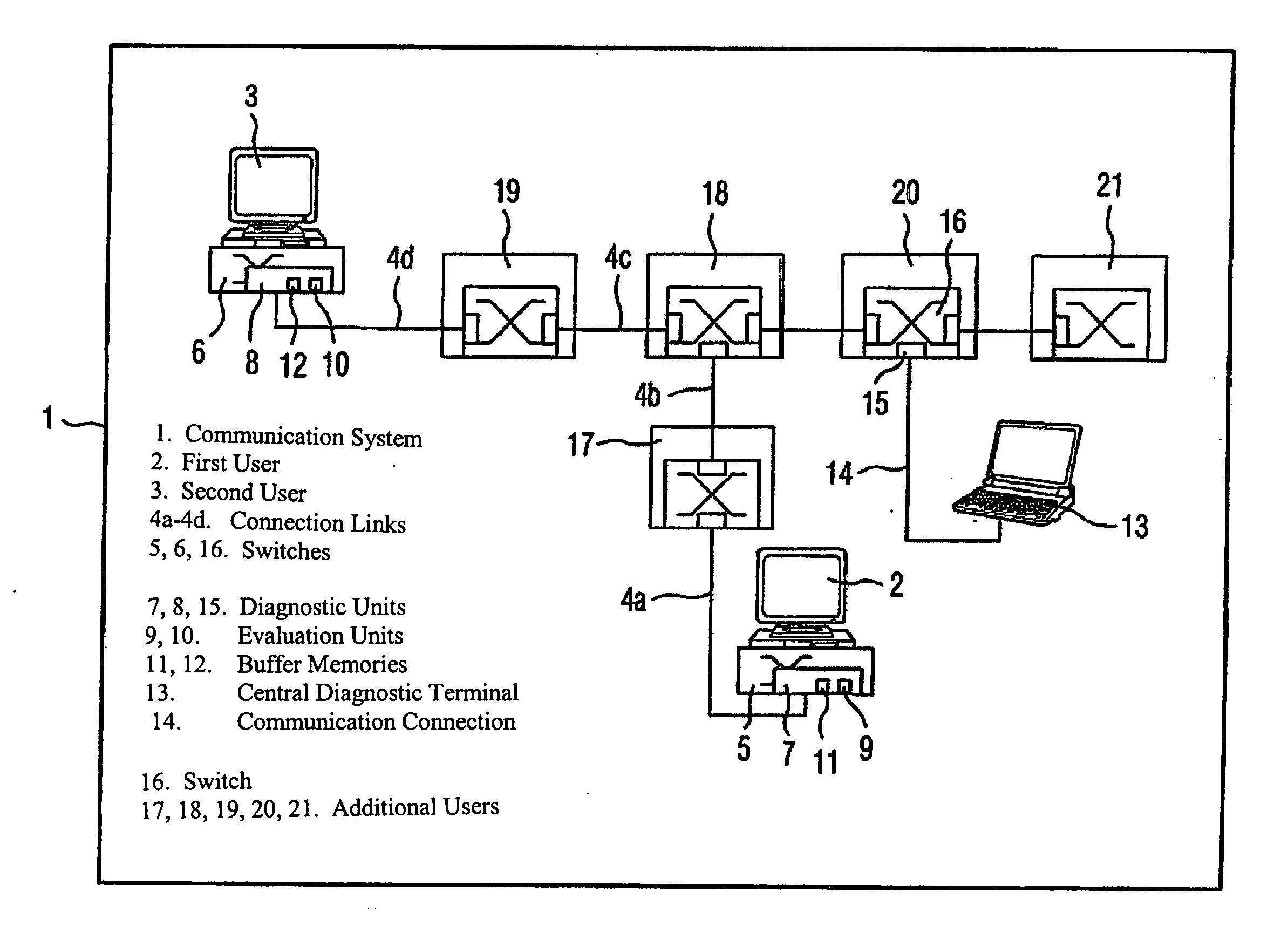
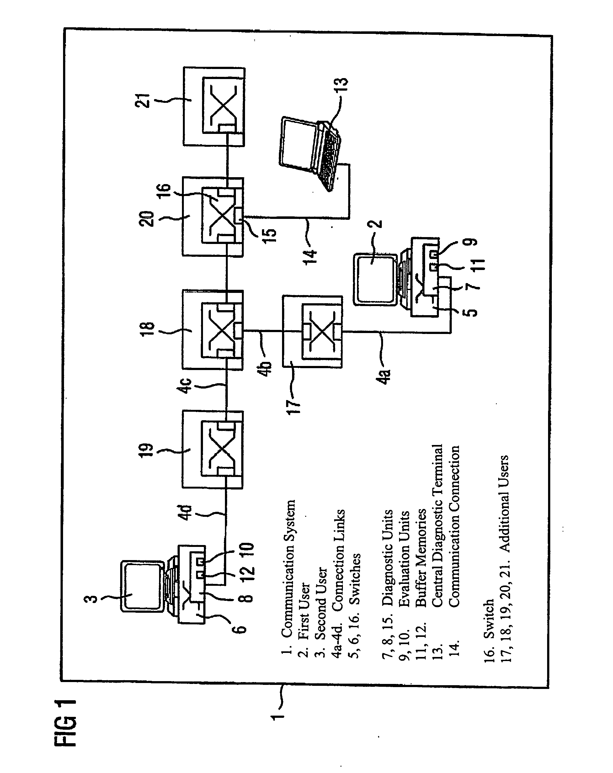
[0035]FIG. 1 shows a block diagram of a communication system 1 according to an exemplary, non-limiting embodiment of the present invention. The depicted communication system 1 represents, for example, a distributed real-time capable automation system. Moreover, this communication system 1 is a switched communication network. For example, it is a real-time Ethernet system. The communication system 1 depicted in FIG. 1 is a cyclically operating system. That is, in this communication system 1, the data are transmitted in one or more transmission cycles.

[0036] The depicted communication system 1 has a plurality of users, which can be simultaneously configured as senders and receivers. Specifically, the communication system 1 has a first user 2, a second user 3, and additional users 17, 18, 19, 20, 21. These users may be configured, for example, as computers and / or automation devices, such as drives.

[0037] Each user of the communication system 1 has an associated coupling unit, which i...


PUM


Abstract

A distributed automation communication system, in particular a real-time critical, cyclic, real-time Ethernet system, which has a plurality of users. Each user has at least one diagnostic unit (7, 8, 15) for the diagnosis and recording of data concerning the data exchange between users. In addition, the communication system (1) has a further user embodied as a central diagnostic terminal (13). The central diagnostic terminal (13) carries out a central diagnosis of the whole communication system (1) by configuration of the diagnostic units (7, 8, 15) of the users and calling up and analyzing the diagnostic data recorded by the diagnostic units (7, 8, 15) of the users.

Description

[0001] This is a Continuation of International Application PCT / DE2003 / 003015, with an international filing date of Sep. 11, 2003, which was published under PCT Article 21(2) in German, and the disclosure of which is incorporated into this application by reference.FIELD AND BACKGROUND OF THE INVENTION [0002] 1. Field of the Invention [0003] The present invention relates to a communication system having users provided with a diagnostic unit. [0004] 2. Description of Related Art [0005] A communication system is defined as a system with at least two users that are interconnected over a data network for the mutual exchange of data or the mutual transmission of data. [0006] Users are, for example, central automation devices, programming, configuration or operating units, peripheral devices, such as input / output modules, drives, actuators, sensors, stored program controllers (SPCs) or other control units, computers or machines that exchange electronic data with other users and, in particul...

Claims


Application Information

Patent Timeline
IPC IPC(8): H04L12/24H04L12/26H04L12/931
CPCH04L12/24H04L12/2602H04L41/00H04L49/351H04L43/00H04L43/106H04L41/069
Inventor FRANKE, MICHAELKRAUSE, KARL-HEINZKOESTNER, MICHAEL
Owner SIEMENS AG
Why Eureka
Try Eureka