
Drive unit for horizontally turning rotational solid

a technology of rotating solids and drive units, which is applied in the direction of manufacturing tools, grain treatment, and gearing, can solve the problem of large height of the required foundation for the gear train, and achieve the effect of less space and cost-effectiveness

Inactive Publication Date: 2005-10-13
MAAG GEAR AG +5
View PDF5 Cites 0 Cited by
  • Summary
  • Abstract
  • Description
  • Claims
  • Application Information

AI Technical Summary

Benefits of technology

[0006] The goal of the present invention, now, consisted in finding a drive unit for such a body of revolution that requires less space at the side in terms of the dimensions than is the case with traditional drive units, and whose foundation can be designed to be small and, thus, cost-effective.
[0008] Thanks to the arrangement, according to the invention, of the gear train housing at the side underneath the body of revolution, the space needed for the overall layout in the sideways direction is substantially decreased. This is due to the fact that at least part of the housing of the gear train comes to lie in the region underneath the body of revolution, and only a part of it still protrudes sideways beyond the contour of the body of revolution.
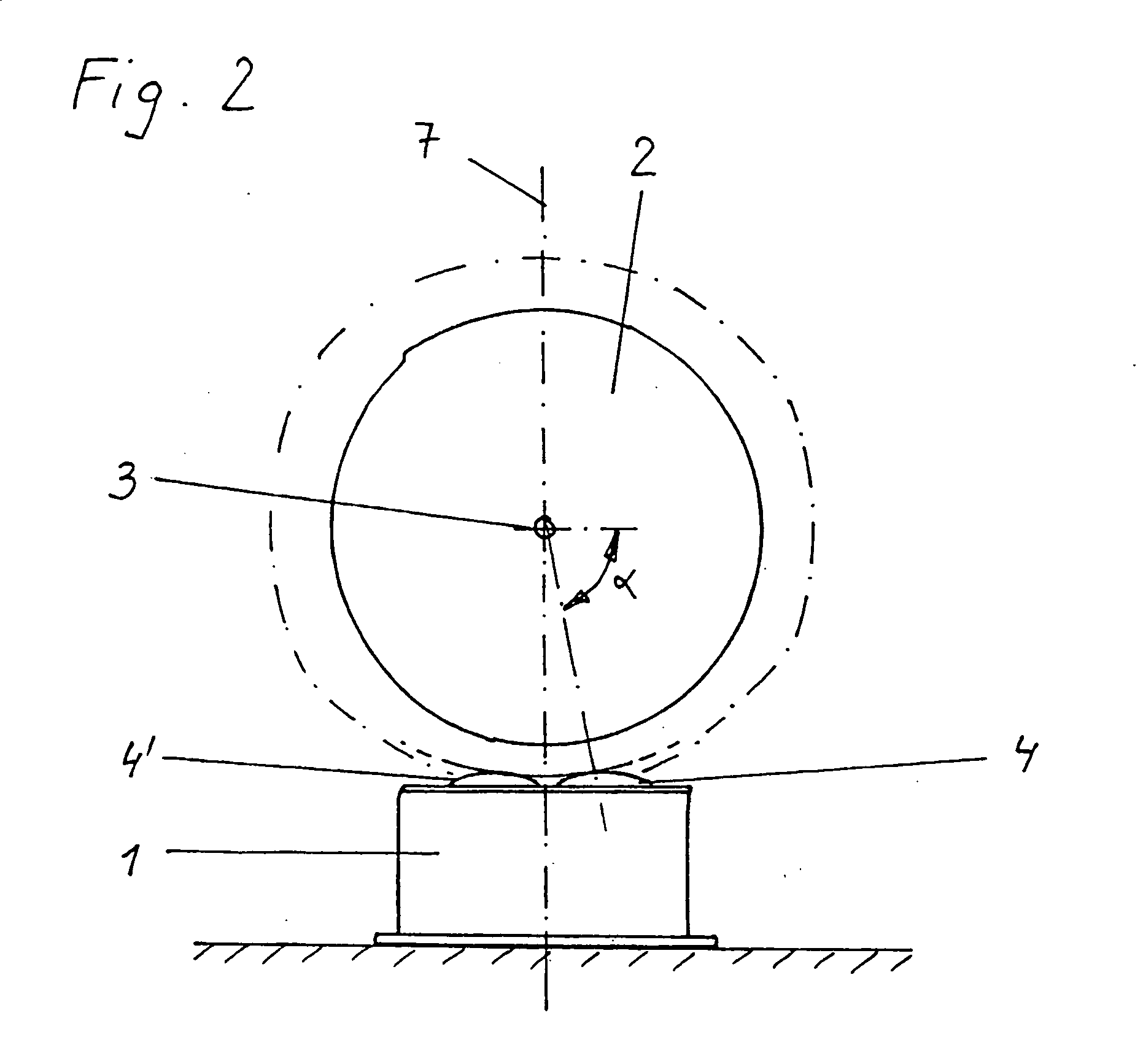
[0009] Preferably, the drive unit is arranged perpendicularly beneath the body of revolution. As a result, the entire housing of the gear train now generally comes to lie within the contour of the body of revolution and no additional space whatsoever and also no additional foundation are required. This has the fuirther advantage that the pinions, if necessary, can also take on the bearing support of the body of revolution arranged thereon, i.e., the corresponding bearings can be replaced or do not even have to be designed as part of the layout. This leads on the whole to further simplification of the construction of the overall layout.
[0010] A further advantage of this arrangement lies in that no additional mounting brackets have to be provided for the drive unit, but instead the drive unit can be placed on the floor or foundation of the layout directly next to the body of revolution. This facilitates both the installation and the maintenance and repair work on the drive unit.

Problems solved by technology

However, the large space required at the side and the large height of the required foundation for the gear train act as drawbacks.

Method used


Image

  • Drive unit for horizontally turning rotational solid
  • Drive unit for horizontally turning rotational solid
  • Drive unit for horizontally turning rotational solid

Examples


Embodiment Construction

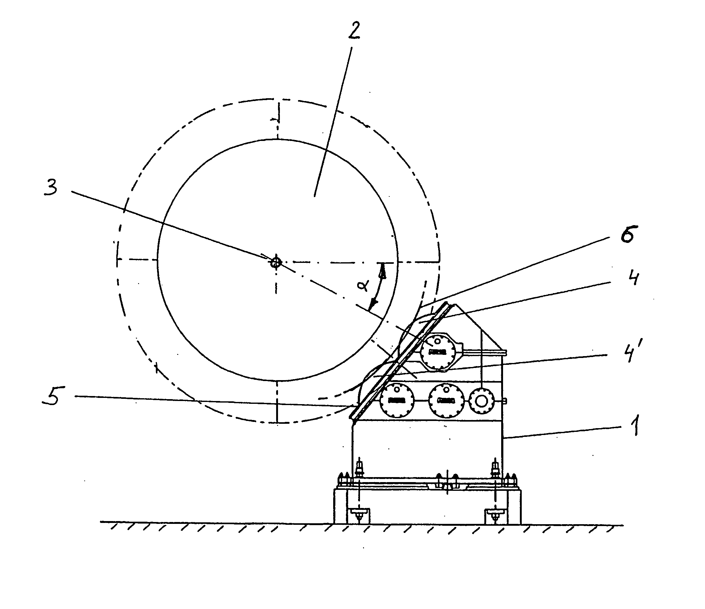
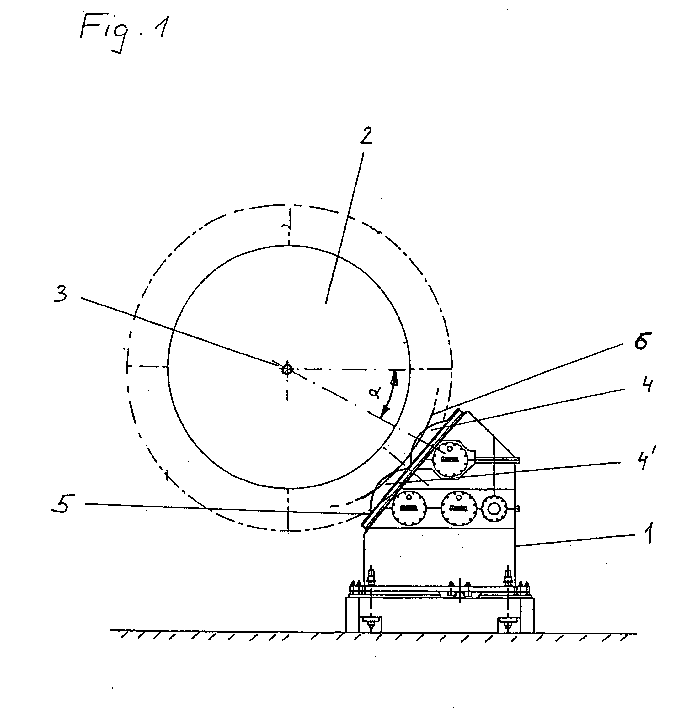
[0016]FIG. 1 shows the gear train housing 1 of the drive unit for a cylindrical body of revolution 2 in end view relative to the axis of rotation 3 of the body of revolution 2. The body of revolution 2, for example, is the grinding drum of a cement mill, and for better clarity the outer contour of this body of revolution is shown only in dashed lines.

[0017] In the gear train housing 1 of the drive unit, the gears are arranged in the form of a speed-reducing gear train, with the two driven gears 4 and 4′ protruding in the direction of the axis of rotation 3 of the body of revolution 2. The teeth of the driven gears 4 and 4′ now engage with the gear rim 6 (only a portion of which is shown) arranged in this place on the periphery of the body of revolution 2. The engaging of the upper driving gear 4 occurs at an angle α of at least approximately 25° to 40° in relation to the horizontal transverse axis of the body of revolution 2. The lower pinion 4′ thus has an angle of engagement of a...


PUM


Abstract

Disclosed is a drive unit for a rotational solid (2) which revolves around the essentially horizontal longitudinal axis (3) thereof. Said drive unit is arranged laterally below the rotational solid (2) such that the driving pinion / s (4, 4′) engage / s in the toothed ring (6) of the rotational solid (3) in a downward direction at an angle between 35° and 90° from the horizontal line. Said arrangement of the housing (1) of the drive unit substantially reduces the lateral space required for the entire installation. Another advantage lies in the fact that the drive unit can be mounted directly on the floor or base of the installation, whereby no additional console or base is needed.

Description

RELATED APPLICATION [0001] This application is a U.S. national stage filing of international application number PCT / CH02 / 00185 filed Apr. 3, 2002.TECHNICAL FILED [0002] The present invention relates to a drive unit for a body of revolution, able to turn about its essentially horizontal lengthwise axis and having at its circumference a gear rim. The drive unit is useful in ball mills and cement mills, for example. BACKGROUND [0003] Large, cylindrical bodies of revolution are used, for example, in ball, rod, or cement mills. Thus, the material being processed is filled into a cylindrical grinding drum, which is arranged to turn about a horizontal axis. [0004] Traditionally, the grinding drum is supported on bearings and has a gear rim generally formed at one end around the circumference, which engages with pinions of the grinding drum's drive unit. In a familiar layout, one pair of pinions engages horizontally sideways with the gear rim of the grinding drum, while the bearings are arr...

Claims


Application Information

Patent Timeline
Patent Type & Authority Applications(United States)
IPC IPC(8): B02C17/24F16H1/22F16H15/00
CPCF16H1/22B02C17/24
Inventor DEEG, THOMASINEICHEN, ARMIN
Owner MAAG GEAR AG
Learn More