
Rapid analysis of functional fluids

a functional fluid and rapid technology, applied in the field of functional fluid analysis, can solve the problems of increasing the cost of the company, increasing the cost of the analysis, and returning to the original source,

Active Publication Date: 2005-10-13
THE LUBRIZOL CORP
View PDF11 Cites 51 Cited by
  • Summary
  • Abstract
  • Description
  • Claims
  • Application Information

AI Technical Summary

Benefits of technology

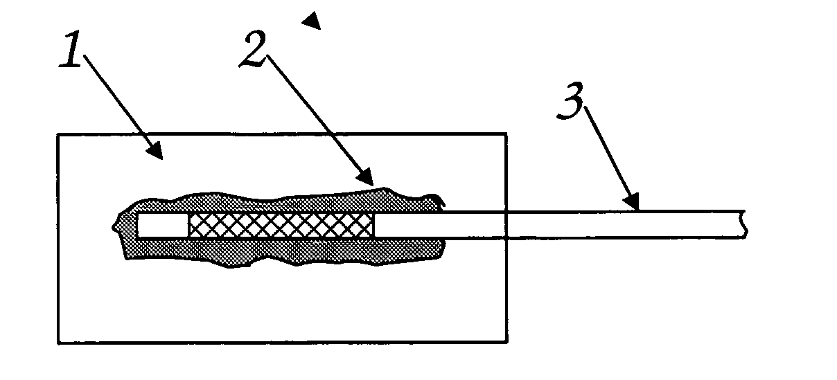
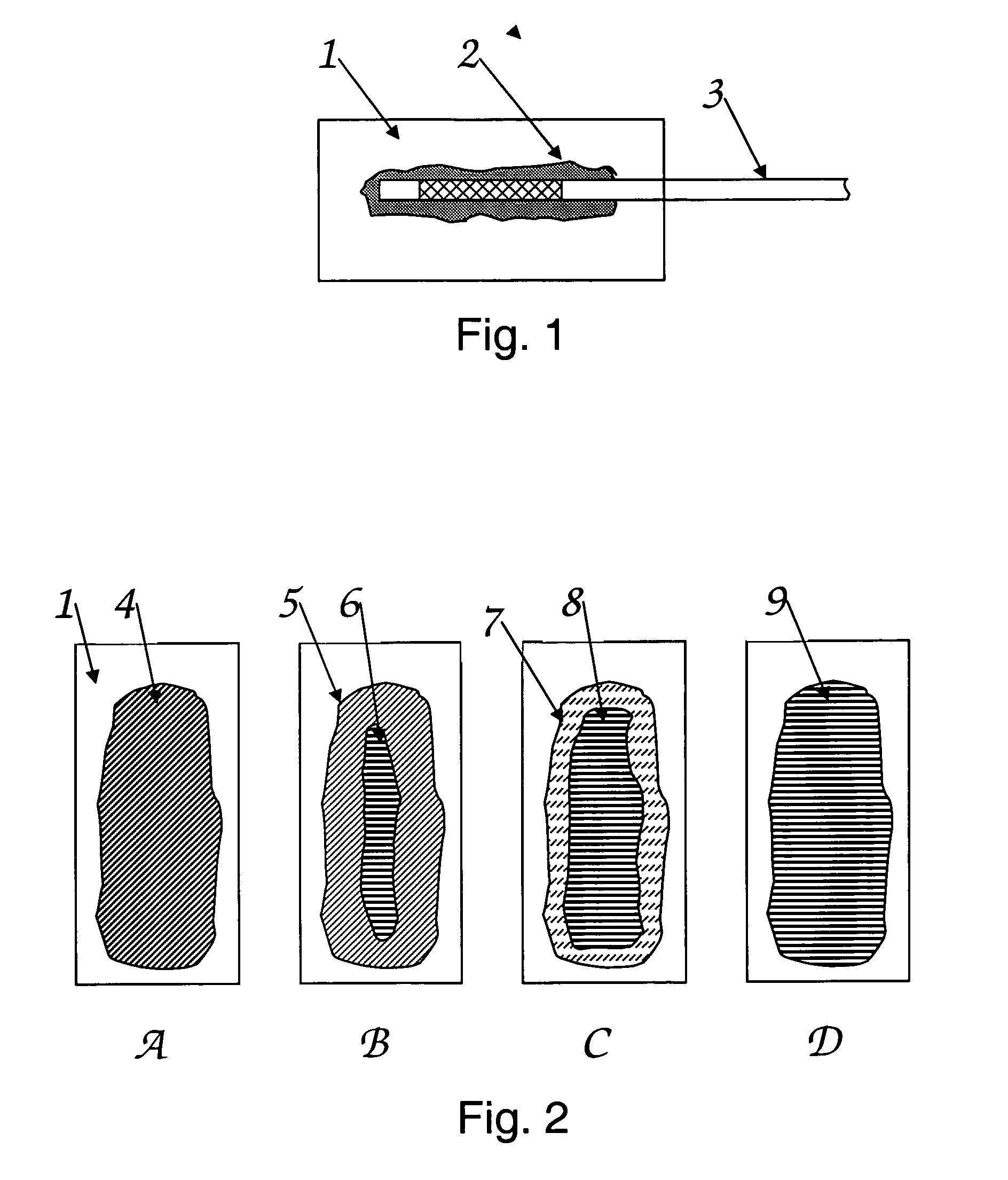
The present invention provides a method to quickly and easily test the quality or identity of functional fluids in the field without precise measurement. This method involves placing a sample of the fluid on a test medium treated with a chemical indicator or developing agent, and analyzing the resulting reaction. The test results show the condition of the fluid, with visual indicia indicating acceptable or unacceptable conditions. The invention also provides a test kit for analysis of functional fluids, including a chemically treated test medium and visual indicia. The method is simple and easy to use in uncontrolled conditions by untrained personnel. The invention also provides a method for detecting marker substances in functional fluids.

Problems solved by technology

These companies often go to great expense to make sure their branded petroleum products meet certain specifications, for example, volatility and octane number, as well as to provide their petroleum products with effective additive packages containing detergents and other components.
Additionally, the extracted, separated phase is classifiable as a hazardous waste and presents problems of safe and lawful disposal, especially when examinations are made “in the field.” Furthermore, the fluid with which was tested may be contaminated, making return to its original source undesirable and presenting additional waste disposal problems.

Method used


Image

  • Rapid analysis of functional fluids
  • Rapid analysis of functional fluids

Examples


specific embodiment

EXAMPLE 1

[0054] This example tests the quality of passenger car engine oil and consists of a test medium of Whatman filter paper, which has been soaked with a solution of ethanol or isopropanol (90% w / w), lauryl alcohol (10% w / w) and pH indicator (0.1% w / w). The pH indicator used is Alizarin (1,2-dihydroxyanthraquinone).

[0055] A used oil sample is placed on the wet filter paper and the basic additives (quantified as the TBN or Total Base Number, typically measured by ASTM D4739) of the oil react with the pH indicator inducing a color change from yellow to purple, with the indicator listed above, to a degree depending on the level of TBN. The intensity of the color change is reduced as the TBN drops over the service life of the oil until no purple color is apparent indicating the fluid has reached its maximum life. (See Table 1)

TABLE 1Effect of TBN on Color ChangeTotal BaseNumberAppearance of the PaperAge of Sample(ASTM D4739)After 1 MinuteAfter 5 MinutesNew5.6 mg KOH / gPurpleStro...


PUM

PropertyMeasurementUnit
concentrationaaaaaaaaaa
timeaaaaaaaaaa
porosityaaaaaaaaaa

Abstract

The invention relates to a method to analyze the condition of a functional fluid comprising: (1) obtaining a sample of the used fluid; (2) placing the sample of the fluid to a test medium; (3) reacting the fluid with an indicator in the test medium; (4) analyzing visually the results of the reactor resulting in the determination of the condition of the fluid. Further an apparatus for analyzing functional fluids is disclosed in the form of a test medium consisting of an absorbent or nonabsorbent material which has been treated with a chemical indicator, marker substance or a developer or detector reagent upon which a sample of the fluid to be tested is placed. The components in the treated test medium react with components in the test fluid providing a visual indication, for example a color change, to judge the condition, the presence of a marker substance or another parameter of the fluid. The functional fluid may be a lubricant, fuel or other functional fluid of innumerable sources, including internal combustion engines, turbines, transmissions, differentials, pumps, metalworking operations, cooling systems, etc, and be either organic solvent or aqueous based.

Description

FIELD OF THE INVENTION [0001] The present invention relates to the analysis of functional fluids, including a method and apparatus for the analysis of functional fluids. In particular the functional fluids that are analyzed include lubricating fluids and fuels, such as those used in automobiles, trucks, engines, turbines, pumps, transmissions, differentials and the like. BACKGROUND OF THE INVENTION [0002] Methods exist for the analysis of functional fluids, including lubricating oils. In particular, methods and apparatus for testing the condition or identity of a fluid include chromatography and chemical analysis. These methods generally require controlled conditions and specialized training. [0003] Other methods and apparatus for assessing the quality of a used fluid include placing a measured amount of fluid upon an absorbent material, heating the sample and awaiting dispersion of the sample. The amount of undispersed sample may then be measured and rated quantitatively. These met...

Claims


Application Information

Patent Timeline
Patent Type & Authority Applications(United States)
IPC IPC(8): G01N21/64G01N21/78G01N31/22G01N33/28
CPCG01N21/78G01N33/2888G01N33/2882G01N31/22G01N33/2876
Inventor RICHARDSON, ROBERT C.VICKERMAN, RICHARD J.BAKER, MARK R.TAYLOR, GREGORY D.GARVIN, GARY A.
Owner THE LUBRIZOL CORP
Learn More