Nose-view monitoring apparatus

a monitoring apparatus and nose-view technology, applied in the direction of navigation instruments, television systems, instruments, etc., can solve the problems of difficult to extract/detect only a mobile object approaching the own vehicle, difficult to extract (detect) these optical flows separately, complicated arrangement and complicated arithmetic operations, etc., to achieve the effect of enhancing safety

Active Publication Date: 2005-10-13
MITSUBISHI MOTORS CORP
View PDF5 Cites 72 Cited by
  • Summary
  • Abstract
  • Description
  • Claims
  • Application Information

AI Technical Summary

Benefits of technology

[0015] The present invention has been developed with a view to eliminating this problem, and it is therefore an object of the invention to provide a nose-view monitoring apparatus capable of detecting an approaching object existing at a lateral position relative to a nose portion of a vehicle with a high degree of accuracy by using a simple logic for notifying information on the approaching object to occupants.

Problems solved by technology

Thus, in a state where the vehicle is in movement, the angle (composition) itself of the nose-view image moves, thereby creating a problem in that a flow vector develops even on an object such as a building or street tree which constitutes the background in the image and which does not move actually and, hence, the background is detected as a mobile object.
Moreover, difficulty is experienced in extracting / detecting only a mobile object approaching the own vehicle from an image taken in a situation that the angle itself varies.
That is, there exists a problem in that a flow vector develops on the entire image due to the movement of the image pickup camera itself, which causes an optical flow developing due to the movement of the own vehicle and an optical flow generated by an actual mobile object to be detected in a state mixed so that difficulty is encountered in extracting (detecting) these optical flows separately.
However, this technique requires not only the moving direction data such as vehicle traveling speed and yaw rate but also the distance to an object to be detected, for calculating the apparent optical flow, i.e., the optical flow developing due to the movement of the own vehicle, which leads to complicated arrangement and complicated arithmetic operations.
Accordingly, the precise optical-flow based recognition of a mobile object such as a vehicle approaching the own vehicle in a nose-view image requires the employment of an arithmetic processing unit with a high processing ability (throughput), which leads to an increase in apparatus cost as a whole.

Method used


Image

  • Nose-view monitoring apparatus
  • Nose-view monitoring apparatus
  • Nose-view monitoring apparatus

Examples


first embodiment

[0052] First of all, a description will be given hereinbelow of a nose-view monitoring apparatus according to a first embodiment of the present invention.

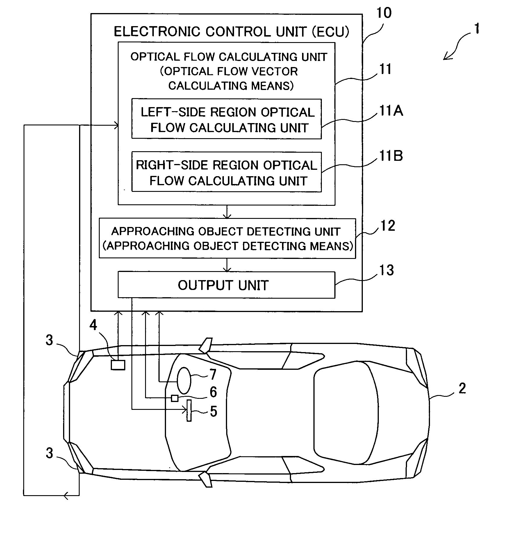
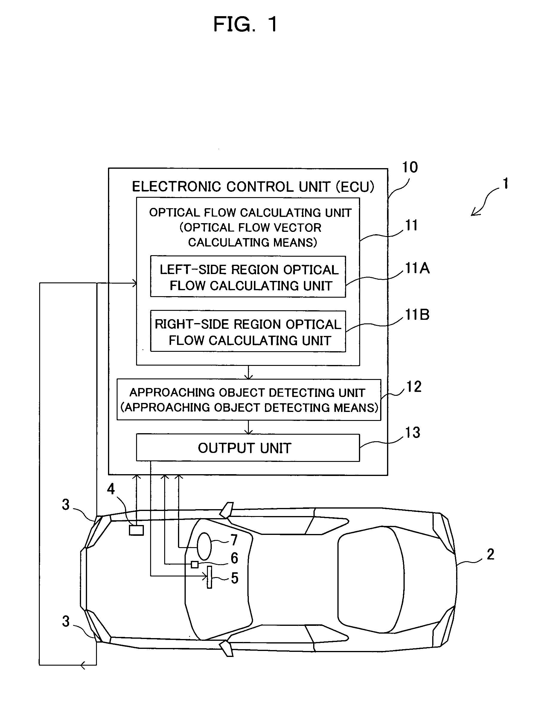
[0053]FIG. 1 shows a vehicle 2 equipped with a nose-view monitoring apparatus 1 according to the present invention. The vehicle 2 is provided with nose-view cameras (image pickup means) 3 each for picking up an image (side-view image) of each of right- and left-side lateral regions relative to the vehicle 2, a vehicle speed sensor (vehicle speed detecting means) 4 for detecting a signal indicative of a traveling speed of the vehicle 2, a nose camera switch 6 serving as a switch for an operation of each of the nose-view cameras 3, a steering angle sensor (steering angle detecting means) 7 for detecting a signal indicative of a steering angle of a steering wheel (or rudder angle of a steered wheel) manipulated by an occupant, an electronic control unit (ECU) 10 and a monitor (notification means) 5 for displaying an image taken throu...

second embodiment

[0100] Furthermore, a description will be given hereinbelow of a nose-view monitoring apparatus according to a second embodiment of the present invention. The same components as those in the first embodiment will be marked with the same reference numerals, and the description thereof will be omitted for brevity.

[0101]FIG. 6 shows a vehicle 2 equipped with a nose-view monitoring apparatus 21 according to a second embodiment of the present invention. The vehicle 2 is provided with nose-view cameras (image pickup means) 3 each for picking up an image of each of right- and left-side lateral regions relative to the vehicle 2, a vehicle speed sensor (turning state corresponding value detecting means) 4 for detecting a signal indicative of a traveling speed of the vehicle 2, a nose camera switch 6 serving as a switch for an operation of each of the nose-view cameras 3, a steering angle sensor (turning direction detecting means / turning state corresponding value detecting means) 7 for detec...

third embodiment

[0144] Furthermore, a description will be given hereinbelow of a nose-view monitoring apparatus 31 according to a third embodiment of the present invention. The same parts as those in the first and second embodiments will be marked with the same reference numerals, and the description thereof will be omitted for simplicity.

[0145]FIG. 8 shows a vehicle 2 equipped with this nose-view monitoring apparatus 31. The vehicle 2 is provided with nose-view cameras (image pickup means) 3 each for picking up an image of each of right- and left-side lateral regions relative to the vehicle 2, a vehicle speed sensor 4 for detecting a signal indicative of a traveling speed of the vehicle 2, a nose camera switch 6 serving as a switch for an operation of each of the nose-view cameras 3, a steering angle sensor (turning direction detecting means) 7 for detecting a signal indicative of a steering angle of a steering wheel (or rudder angle of a steered wheel) manipulated by an occupant, an electronic c...


PUM


Abstract

The present invention relates to a nose-view monitoring apparatus, and it is an object of the invention to detect an approaching object existing in lateral regions relative to a nose portion of a vehicle with high accuracy for notifying the information on the approaching object to an occupant. The nose-view monitoring apparatus comprises an image pickup unit provided on a nose of the vehicle for picking up a side-view image with respect to the vehicle, an optical flow vector calculating unit for calculating an optical flow vector on the basis of the image, an approaching object detecting unit for detecting the approaching object on the basis of, of the optical flow vectors calculated by the optical flow vector calculating unit, an optical flow vector having a vector component along a traveling direction of the vehicle in the image, and a notification unit for displaying the image and further for notifying the fact of the detection of the approaching object.

Description

BACKGROUND OF THE INVENTION [0001] (1) Field of the Invention [0002] The present invention relates to a nose-view monitoring apparatus designed to display a pickup image taken through a nose-view camera(s) and further to extract optical flow vectors from the pickup image. [0003] (2) Description of Related Art [0004] So far, there has been developed a technique in which an image pickup camera is located at a nose (front end) portion of a vehicle so as to pick up a side-view image (right- and / or left-side image of lateral regions) and each of the pickup image (so-called nose-view image) is displayed on a monitoring apparatus or the like for supplementing the occupant's unaided vision. In general, in such a technique, a monitoring apparatus, which is designed to display a pickup image, is also used as an in-vehicle monitor made to display a television image, a car navigation image (screen display with car navigation system) or the like, and a television image or a navigation image is d...

Claims


Application Information

Patent Timeline
Patent Type & Authority Applications(United States)
IPC IPC(8): B60R1/00B60R1/10B60R11/00G01C11/04G06T7/20H04N7/18
CPCB60R1/00B60R2300/105B60R2300/30H04N7/181B60R2300/404B60R2300/802B60R2300/302
Inventor MAEMURA, TAKAHIROIKEYAMA, MASAHIRODURUCAN, EMRULLAH
Owner MITSUBISHI MOTORS CORP
Why Eureka
Try Eureka