
Method for refining traffic flow data

a traffic flow and data technology, applied in the field of vehicle navigation system, can solve the problems of wasting precious bandwidth, inflexible and cumbersome methods for providing and utilizing traffic information for navigation, and many vehicles that require the same information, so as to achieve the effect of reducing traffic congestion

Active Publication Date: 2005-10-06
HONDA MOTOR CO LTD
View PDF99 Cites 117 Cited by
  • Summary
  • Abstract
  • Description
  • Claims
  • Application Information

AI Technical Summary

Benefits of technology

[0012] Yet another aspect of the present invention is to provide a system that alleviates traffic congestion. In general, the system monitors the location and speed of each vehicle on the road in relation to a specific traffic signal. In one embodiment, the system modifies the signal strength of the traffic signal based, in part, on speed and distance factors. For example, the system will not modify the signal of the traffic signal until the speed differential between vehicles traveling in adjacent lanes is less than twenty miles per hour. In another embodiment, the system modifies the signal strength of the traffic signal based, in part, on the speed differential and the distance that a specific vehicle is located form the traffic signal.

Problems solved by technology

Conventionally, however, known methods for providing and utilizing the above-described traffic information for navigation remain very inflexible, cumbersome, and inefficient.
A drawback with this method is that many vehicles require the same information.
This method, therefore, requires the transmittal of the same information several times to a plurality of vehicles, which results in a waste of precious bandwidth.
As known in the art, wireless network bandwidth is extremely sensitive to network capacity.
The drawback with these methods is that many vehicles are inundated with a large amount of unwanted traffic information.

Method used


Image

  • Method for refining traffic flow data
  • Method for refining traffic flow data
  • Method for refining traffic flow data

Examples


Embodiment Construction

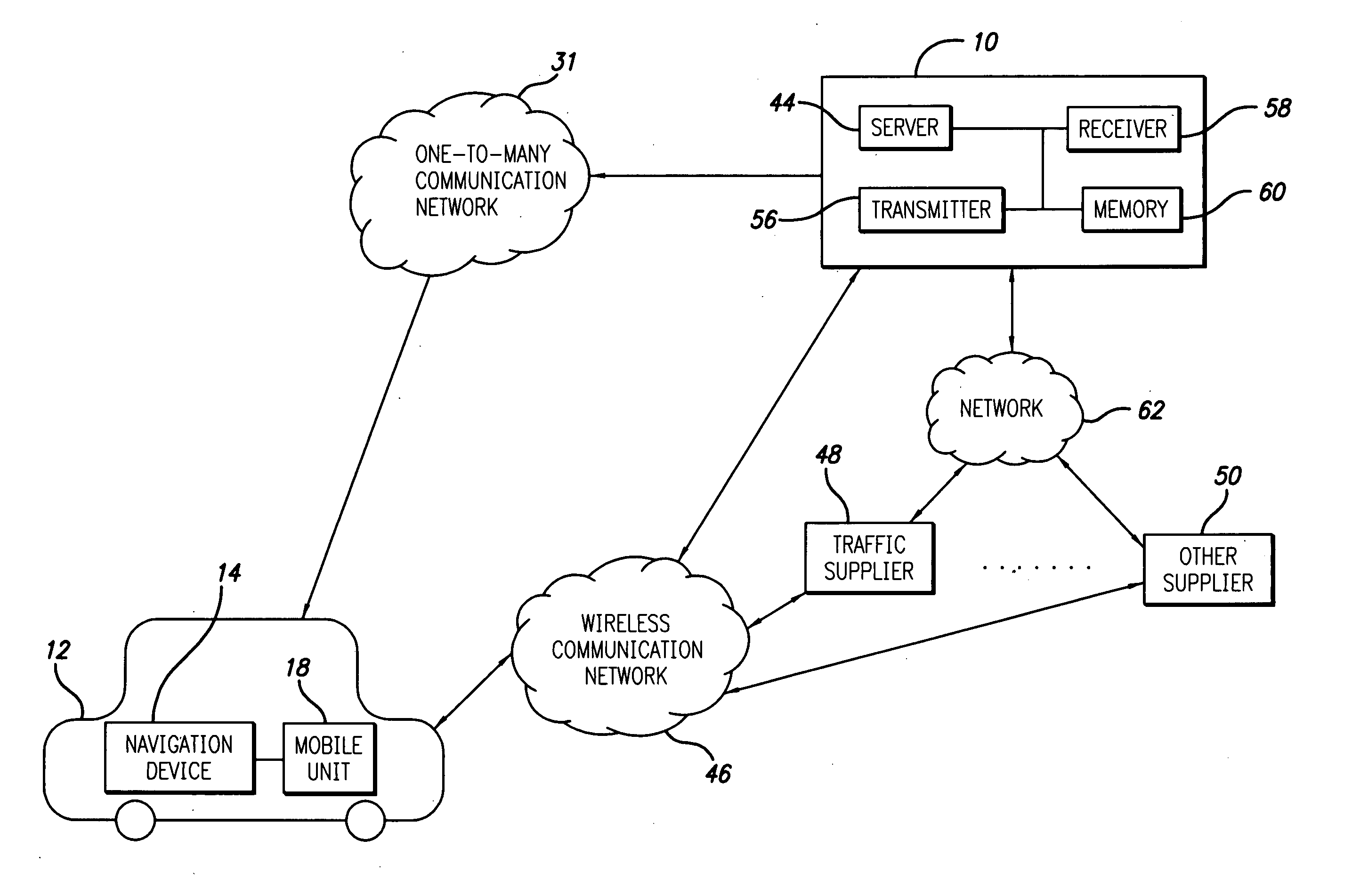
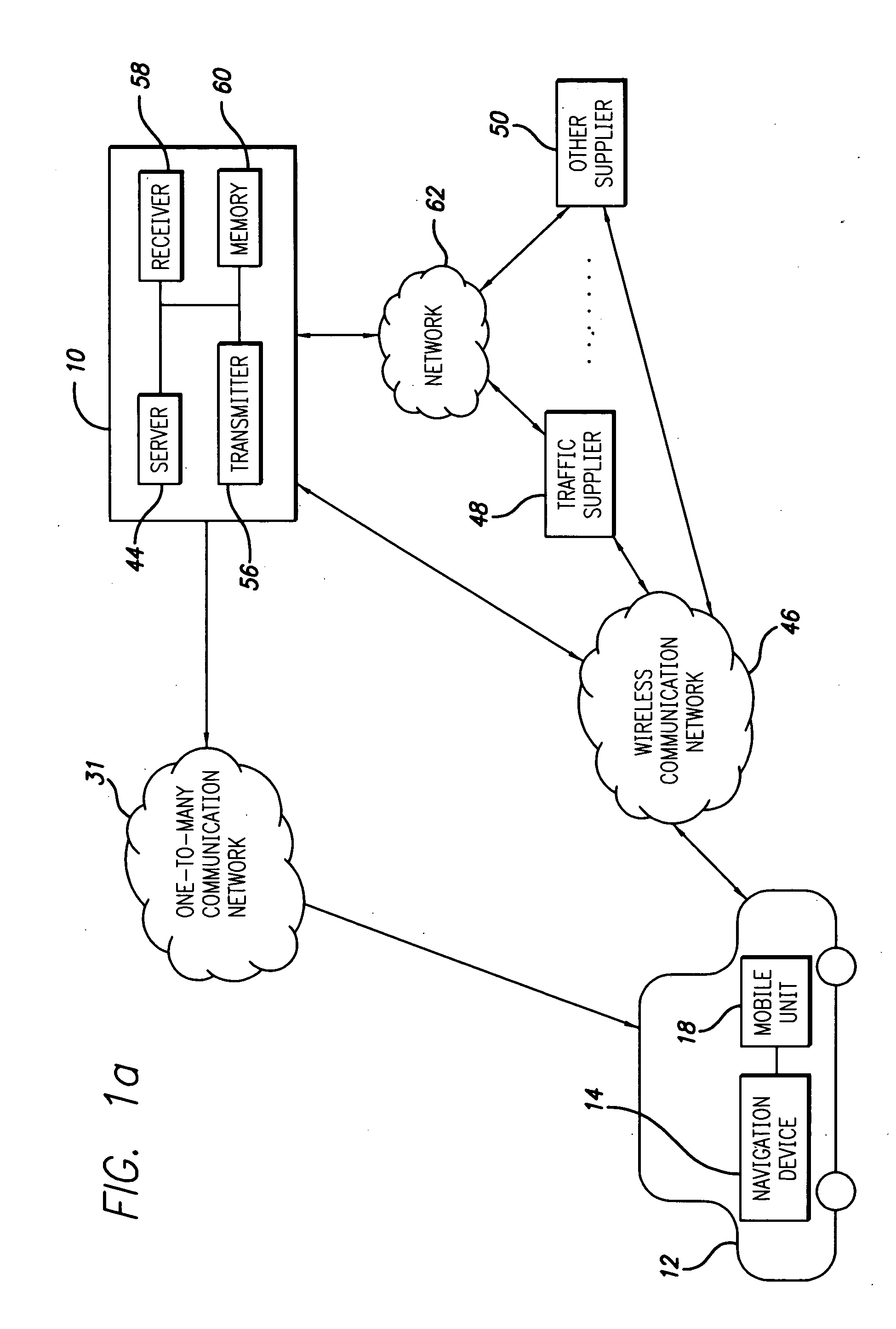
[0068] The present invention is directed to a system and method for facilitating the exchange of traffic information between a remote location and a vehicle. In particular, the present invention is directed to a system and method that includes a vehicle that exchanges traffic information with the remote location by way of one or more communication networks in a manner that conserves bandwidth while providing sufficient traffic information to the vehicle.

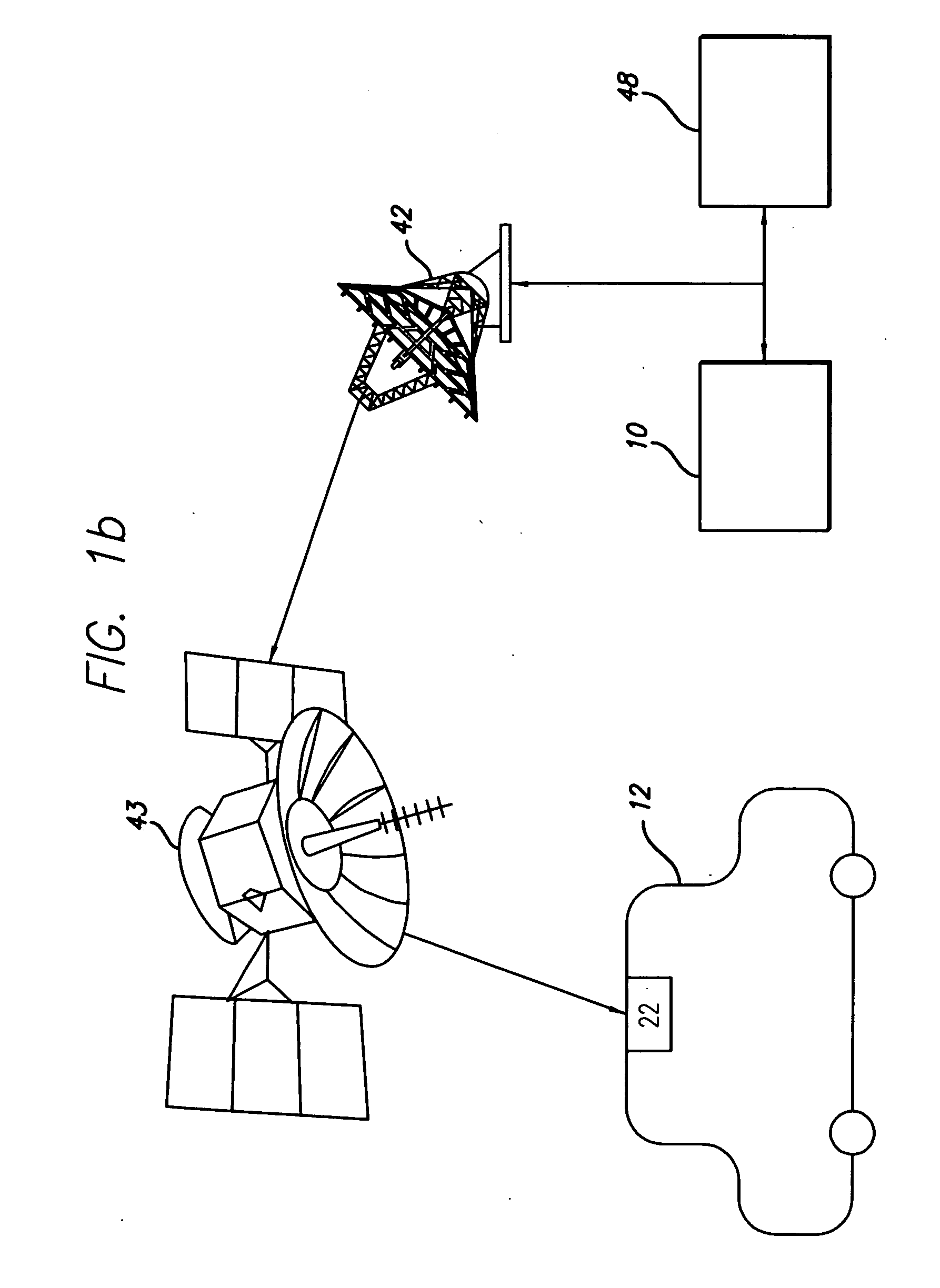
[0069]FIG. 1a shows a first embodiment of a system for facilitating the exchange of information between a remote location 10 and a vehicle 12 pursuant to aspects of the invention. The vehicle 12 includes a navigation device 14. Referring now also to FIG. 1c, the navigation device 14 may include an output unit 21, a receiver unit 22, an input unit 23, a position detection unit 25, a navigation memory unit 30, a navigation processor unit 26, and an RF transceiver unit 52 that are all in electrical communication with one another. The n...


PUM


Abstract

Traffic information, including traffic flow information and traffic incident information, obtained through a traffic management system for providing and facilitating the exchange of traffic information between a remote location and a vehicle may be presented to a user on a user display in the vehicle. In one embodiment, traffic information provided to a vehicle navigation device is refined by comparing the average speed of the vehicle against the average speed of other vehicles traveling along the same road. In another embodiment, the operation of a traffic signal is controlled based, in part, on the current traffic flow and distance from the traffic signal to alleviate traffic congestion.

Description

RELATED APPLICATION INFORMATION [0001] This application claims priority to U.S. Provisional Application Ser. No. 60 / 560,087, entitled “Method and System for Traffic Management Between a Vehicle and Remote Location,” which was filed with the U.S. Patent and Trademark Office on Apr. 6, 2004.BACKGROUND OF THE INVENTION [0002] 1. Field of the Invention [0003] The present invention generally relates to a vehicle navigation system. More specifically, the present invention relates to a vehicle navigation system that provides traffic information to a user of the vehicle navigation system based at least in part on user preferences. [0004] 2. Description of Related Art [0005] Navigation systems for determining a route from a start point to a destination point are well known in the art. In addition, navigation systems having capabilities for determining the geographic position of a reference point are also well known in the art (e.g., a Global Positioning System (GPS) or a self-contained syste...

Claims


Application Information

Patent Timeline
IPC IPC(8): G08G1/0968G01C21/26G08G1/01G08G1/0967
CPCG01C21/26G08G1/0104G08G1/096716G08G1/096741G08G1/096775G08G1/096827G08G1/096844
Inventor UYEKI, ROBERT
Owner HONDA MOTOR CO LTD
Learn More