
Robot and a robot control method

a robot and control method technology, applied in the field of robot and robot control method, can solve the problems of not supporting the user, camera and robot cannot previously support prevention of burglary, and camera and robot cannot previously support prevention

Inactive Publication Date: 2005-10-06
KK TOSHIBA
View PDF5 Cites 14 Cited by
  • Summary
  • Abstract
  • Description
  • Claims
  • Application Information

AI Technical Summary

Benefits of technology

[0010] According to still another aspect of the present invention, there is also provided a computer program product, comprising: a computer readable program code embodied in said product for causing a computer to control a robot, said computer readable program code comprising: a first program code to store a plurality of check works and check places to execute each check work locally in case of a user's departure in a memory; a second program code to select check works to be executed from the memory; a third program code to generate an execution order of selected check works; a fourth program code to move the robot to a check place to execute a selected check work according to the execution order; a fifth program code to record an execution result of each of the selected check works; and a sixth program code to present the execution result to the user.

Problems solved by technology

However, these camera and robot (disclosed in above three references) can not support the user to previously prevent a crime or a disaster indoors.
However, the camera and robot can not previously support prevention for intrusion of the burglar.
However, these camera and robot can not previously support prevention for leaving the thing in the house.

Method used


Image

  • Robot and a robot control method
  • Robot and a robot control method
  • Robot and a robot control method

Examples


first embodiment

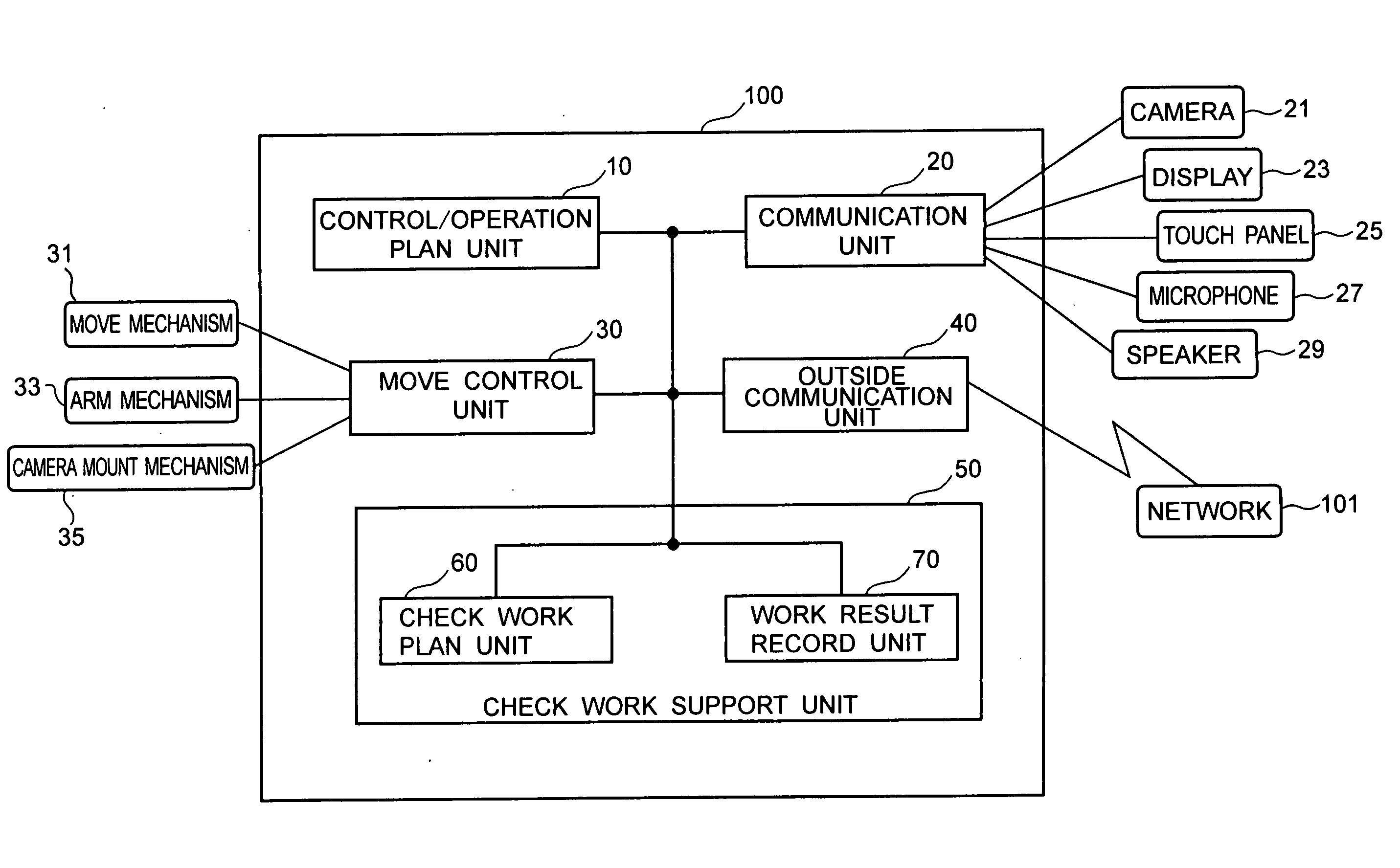
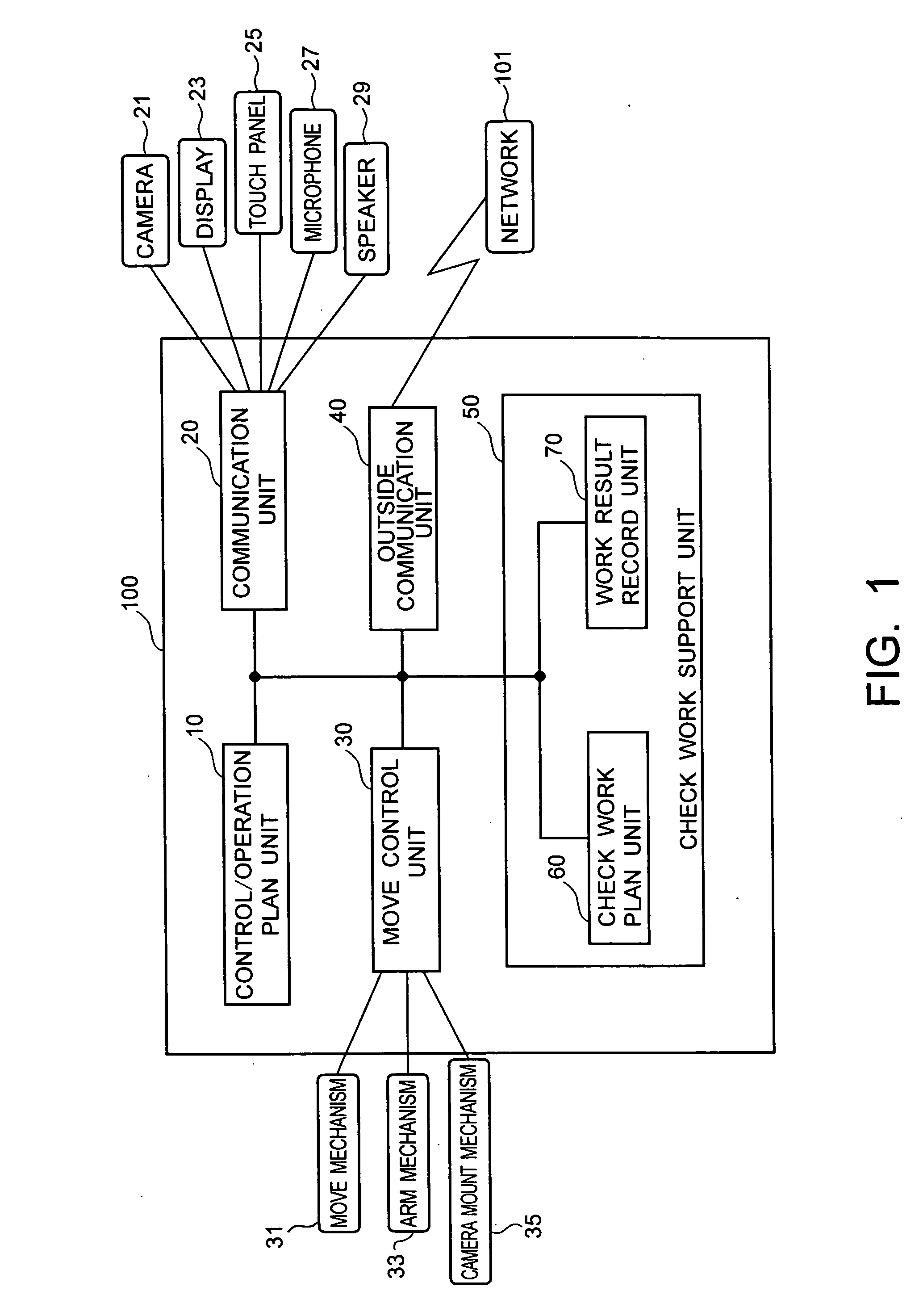
[0021] Hereinafter, various embodiments of the present invention will be explained by referring to the drawings. FIG. 1 is a block diagram of a robot 100 for supporting a departing or remote user according to a The robot 100 includes a control / operation plan unit 10, a communication unit 20, a move control unit 30, an outside communication unit 40, and a check work support unit 50. Furthermore, the communication unit 20 connects with a camera 21, a display 23, a touch panel 25, a microphone 27, and a speaker 29. The move control unit 30 connects with a move mechanism 31, an arm mechanism 33, and a camera mount mechanism 35.

[0022] The control / operation plan unit 10 controls each unit of the robot 100, and plans a work operation of the robot 100. For example, the control / operation plan unit 10 stores map information as the robot's movable area, and generates a move route of the robot 100 based on the map information. As a result, the robot 100 can autonomously move indoors.

[0023] Th...

second embodiment

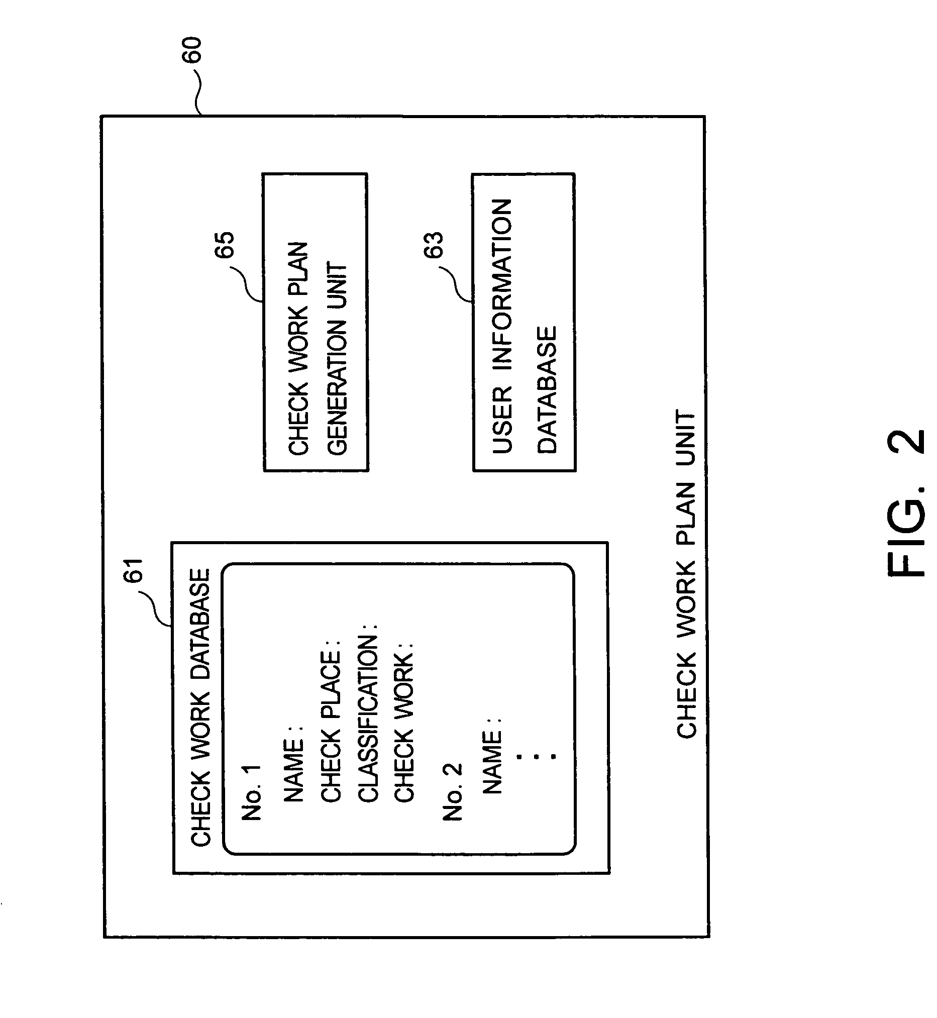
[0047] In the second embodiment, the user information database 63 stores numbers of task data corresponding to each user, and a schedule of the user. This schedule may be previously registered by the user through the touch panel 25 or may be input by the user though the microphone 27 when the user goes out. The check work database 61 stores a name of check object (For example, belongings), a coordinate of check place, a classification of check object (For example, umbrella), contents of check work (For example, check of bringing), and a condition (For example, precipitation possibility is above 30%). These data are called as task data.

[0048]FIG. 8 is a flow chart of processing of the robot control method according to the second embodiment. As shown in FIG. 8, first, the robot 100 executes the user identification (S10). The user identification method is the same as the first embodiment.

[0049] The check work plan generation unit 65 obtains the schedule from the user information datab...

third embodiment

[0056] In the third embodiment, the user information database 63 stores the user's current place (location), the user's current dress, the user's past dress, and the user's schedule. These data may be previously registered by the user through the touch panel 25, or may be input by the user through the microphone 27 when the user goes out. Furthermore, information of the user's present dress and past dress may be image data input by the camera 21. The check work database 61 stores a name of check object (For example, dress), a coordinate of check place, a classification of check object (For example, a jacket), and contents of check work (For example, check of difference).

[0057]FIG. 10 is a flow chart of processing of the robot control method according to the third embodiment. As shown in FIG. 10, first, the robot 10 executes the user identification (S10). The user identification method is the same as in the first embodiment.

[0058] The check work plan generation unit 65 obtains the s...


PUM


Abstract

A robot is autonomously moved locally by a move mechanism. In the robot, a check work memory stores a plurality of check works and check place to execute each check work in case of a user's departure to a remote location. A check work plan unit selects check works to be executed from the check work memory and generates an execution order of selected check works. A control unit controls the move mechanism to move the robot to a check place to execute a selected check work according to the execution order. A work result record unit records an execution result of each of the selected check works. A presentation unit presents the execution result to the user.

Description

CROSS-REFERENCE TO RELATED APPLICATIONS [0001] This application is based upon and claims the benefit of priority from prior Japanese Patent Application P2004-109001, filed on Apr. 1, 2004; the entire contents of which are incorporated herein by reference. FIELD OF THE INVENTION [0002] The present invention relates to a robot and a robot control method for supporting an indoor check work before a user goes out. BACKGROUND OF THE INVENTION [0003] Recently, in order to monitor a person's home while he is away, a remote monitor camera and a caretaking robot are developed. For example, the remote monitor camera is disclosed in “Toshiba's network camera “IK-WB11”, Internet<URL:http: / / www.toshiba.co.jp / about / press / 2003—08 / pr_j2501. htm>”. This remote monitor camera is connected to an Intranet or an Internet, and delivers a video to PC (Personal Computer) in real time. Furthermore, this robot camera can change direction in response to a remote operation from a PC browser screen. [0004...

Claims


Application Information

Patent Timeline
Patent Type & Authority Applications(United States)
IPC IPC(8): B25J5/00B25J13/00
CPCB25J9/0003B25J19/023
Inventor YOSHIMI, TAKASHISUZUKI, KAORUYAMAMOTO, DAISUKEHIROKAWA, JUNKONAKAMOTO, HIDEICHITAMURA, MASAFUMIMIYAZAKI, TOMOTAKAKAWABATA, SHUNICHI
Owner KK TOSHIBA
Learn More