
Boneless spiral sliced meat product and method of slicing the same

a spiral slicing and meat technology, applied in metal working apparatus, meat/fish preservation, food science, etc., can solve the problems of limited brother's device, inability to use a boneless cut of meat which has no support structure, etc., and achieve the effect of preventing the blade from cutting and allowing the engagement force to be easily overcom

Inactive Publication Date: 2005-10-06
LOGAN JAMES P JR
View PDF0 Cites 0 Cited by
  • Summary
  • Abstract
  • Description
  • Claims
  • Application Information

AI Technical Summary

Benefits of technology

"The present invention provides an improved meat slicing accessory that can make spiral cuts in hams or other meats, including boneless meats. The accessory includes a chuck assembly for holding and rotating the meat, a blade for cutting the meat, a linear indexing system for moving the slicer blade, a positioning system for moving the slicer blade into cutting engagement with the meat, a rotational stop for limiting blade engagement during boneless meat cutting operations, and an improved meat spit for providing structural support for boneless meats during cutting operations. The linear indexing means include a threaded drive shaft and a blade assembly mounted on the drive shaft. The blade positioning system is a rotating system linked to the blade rotator sleeve, which causes the slicer blade to engage or disengage the meat. The positioning means permits the engagement force to be readily overcome, thereby preventing the blade from cutting into bones or joints in the meat which are located eccentric with respect to the chuck axis of rotation."

Problems solved by technology

First, they typically include a rotating chuck assembly.
However, all of these devices rely on the center bone to provide structural support for the meat.
These devices cannot be used with a boneless cut of meat which has no support structure of its own.
However, the Brother's device is limited to the use of both adjustable upper prong members and lower vertically adjustable lower stop member slidably carried by a cruciform shaped spit.

Method used


Image

  • Boneless spiral sliced meat product and method of slicing the same
  • Boneless spiral sliced meat product and method of slicing the same
  • Boneless spiral sliced meat product and method of slicing the same

Examples


Embodiment Construction

[0024] In describing a preferred embodiment of the present invention illustrated in the drawings, specific terminology is employed for the sake of clarity. However, the invention is not intended to be limited to the specific terminology so selected, and it is to be understood that each specific element includes all technical equivalents which operate in a similar manner to accomplish a similar purpose.

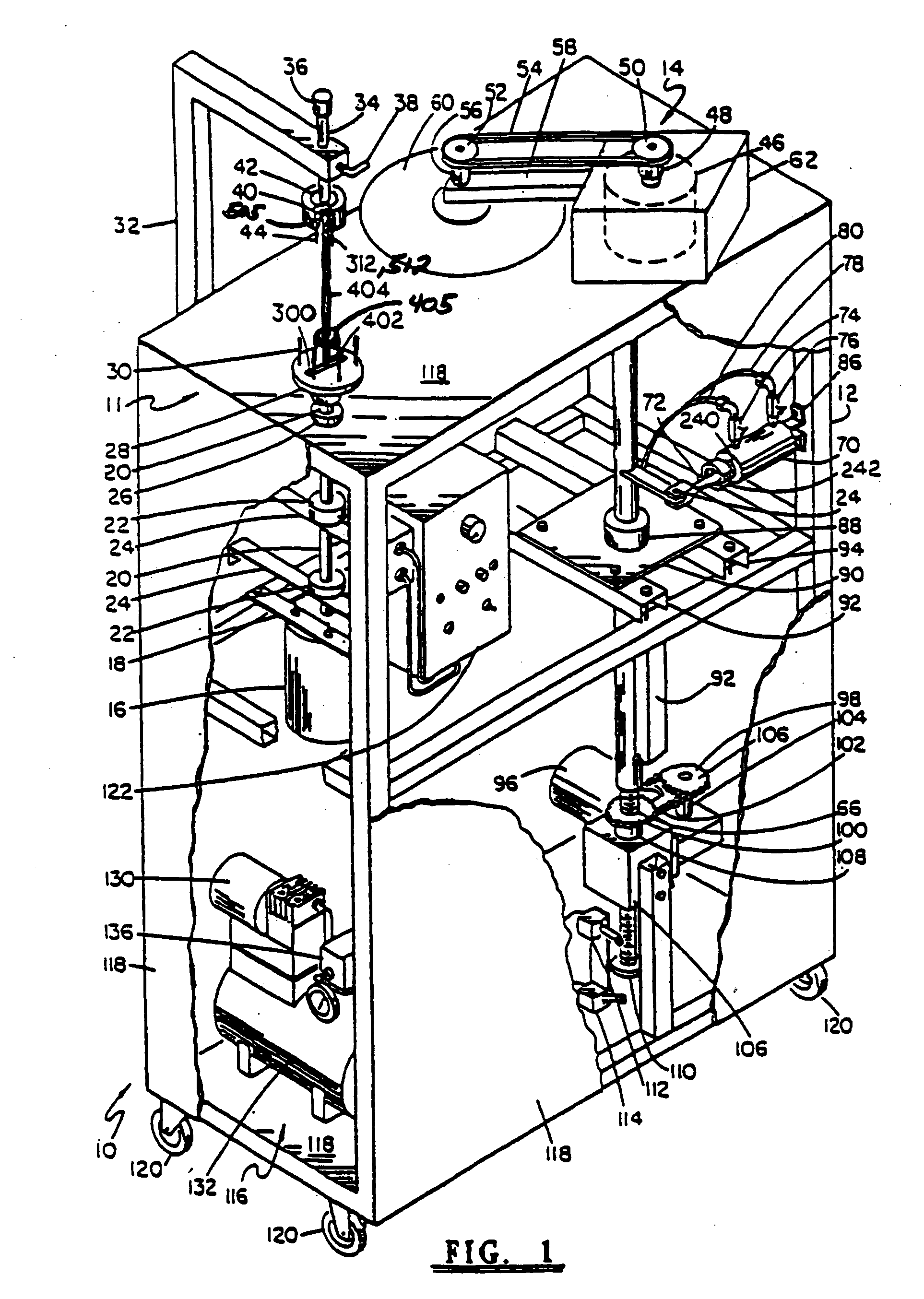
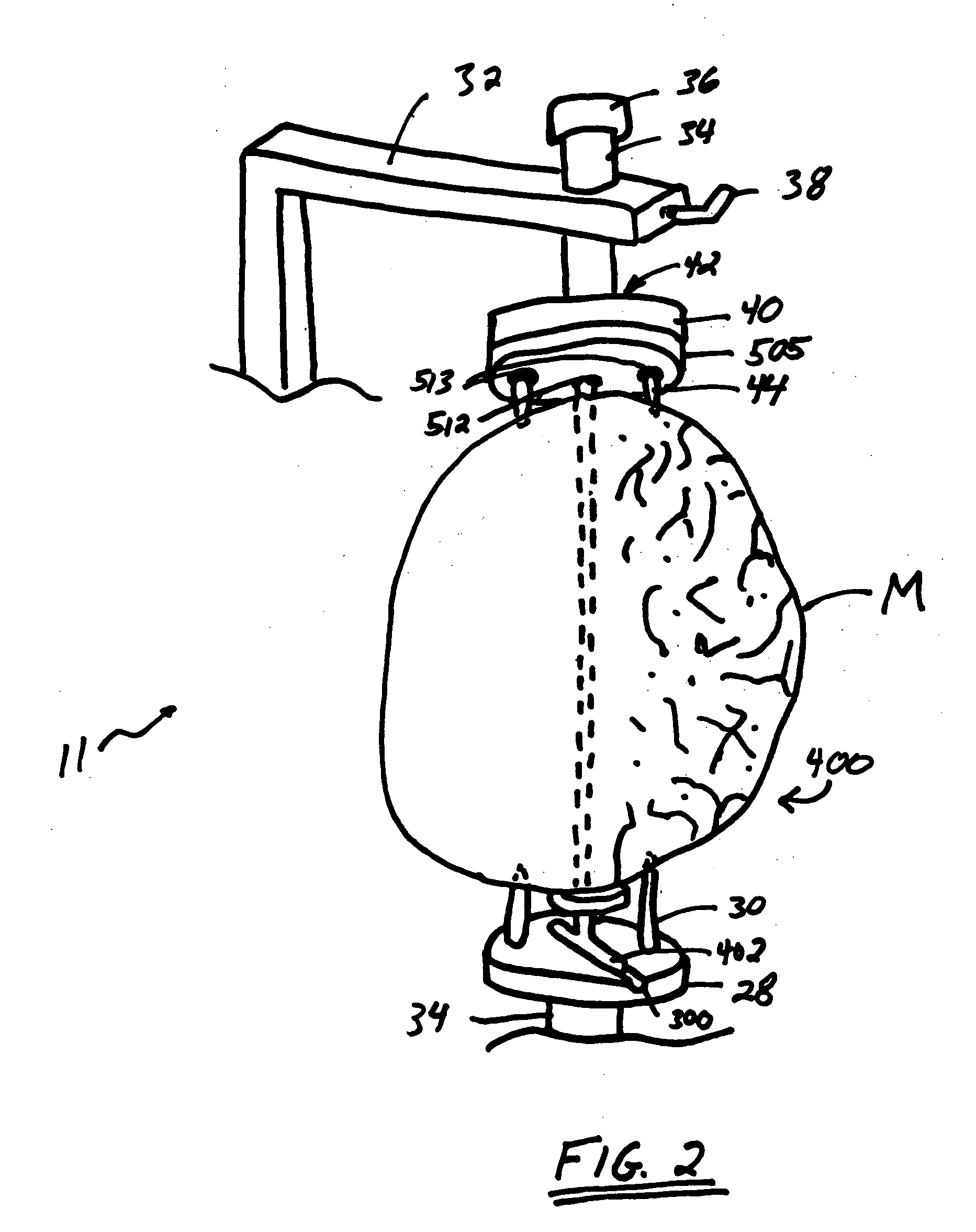
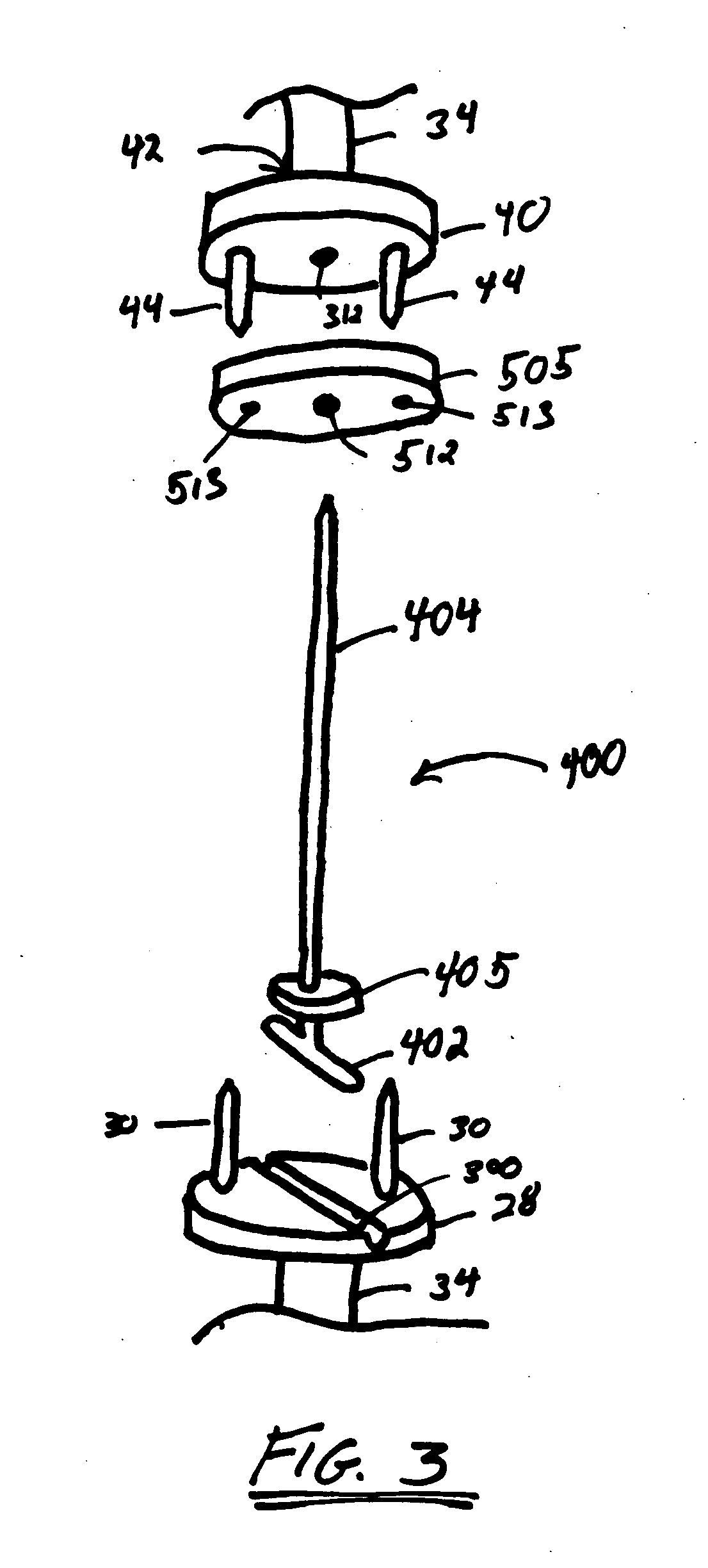
[0025] Referring now to FIG. 1, there is a partial depiction of a meat slicing apparatus 10 for spiral slicing a boneless cut of meat of the type disclosed in Logan, Jr. U.S. Pat. Nos. 4,821,635, 5,030,472, and Re. 35,374, which is expressly incorporated herein by reference in their entireties. Apparatus 10 comprises a knife blade 60 which includes a meat chuck assembly 11, a positioner assembly 13, a slicer assembly 14, linear indexing assembly 15 and a main frame 12 used to support the chuck and slicer assemblies 11 and 14 and other components of the apparatus.

[0026] Referring now ...


PUM


Abstract

A meat product is spirally sliced around an axis through the meat created by the insertion of a temporary support member through the meat. The meat is mounted in meat slicing apparatus which rotates the meat. A slicer blade is introduced into the meat in a plane substantially perpendicular to the axis of rotation while the meat is rotating. The slicer blade is then indexed linearly along an axis parallel to the axis of rotation of the meat, thereby effecting a continuous spiral cut in the meat. First and second spacers are used to allow the meat product to have a continuous spiral cut having first and second ends each residing writing a range of ⅛ of an inch to 1 inch from the respective ends of the meat product.

Description

RELATED APPLICATION [0001] This application is a continuation of U.S. patent application Ser. No. 10 / 040,163, filed Oct. 19, 2001.BACKGROUND OF THE INVENTION [0002] 1. Field of the Invention [0003] The present invention relates to an improved apparatus for the spiral slicing of boneless meat products and, more particularly, the improved apparatus relates to an accessory for use with a spiral meat slicing machine designed for effecting a spiral slice cut in a ham, beef roast, turkey or the like. [0004] 2. General Background [0005] There exists a number of different apparatus for spiral slicing of meats, such as hams or roasts, about the bone located in the cut of meat. These devices have a number of common features. First, they typically include a rotating chuck assembly. The chuck assembly is driven by some motorized means and is designed to hold the meat to be cut, thereby rotating the meat about the chuck assembly rotational axis. Second, the device, includes a saw blade, disposed...

Claims


Application Information

Patent Timeline
Patent Type & Authority Applications(United States)
IPC IPC(8): A23L13/00
CPCA23L13/00
Inventor LOGAN, JAMES P. JR.
Owner LOGAN JAMES P JR
Learn More