
Method of retrieving image data of a moving object, apparatus for photographing and detecting a moving object, and apparatus for retrieving image data of a moving object

a technology for moving objects and image data, applied in the field of retrieving image data of moving objects, can solve the problem of taking a long time to retrieve images

Inactive Publication Date: 2005-10-06
FUJITSU LTD
View PDF9 Cites 96 Cited by
  • Summary
  • Abstract
  • Description
  • Claims
  • Application Information

AI Technical Summary

Benefits of technology

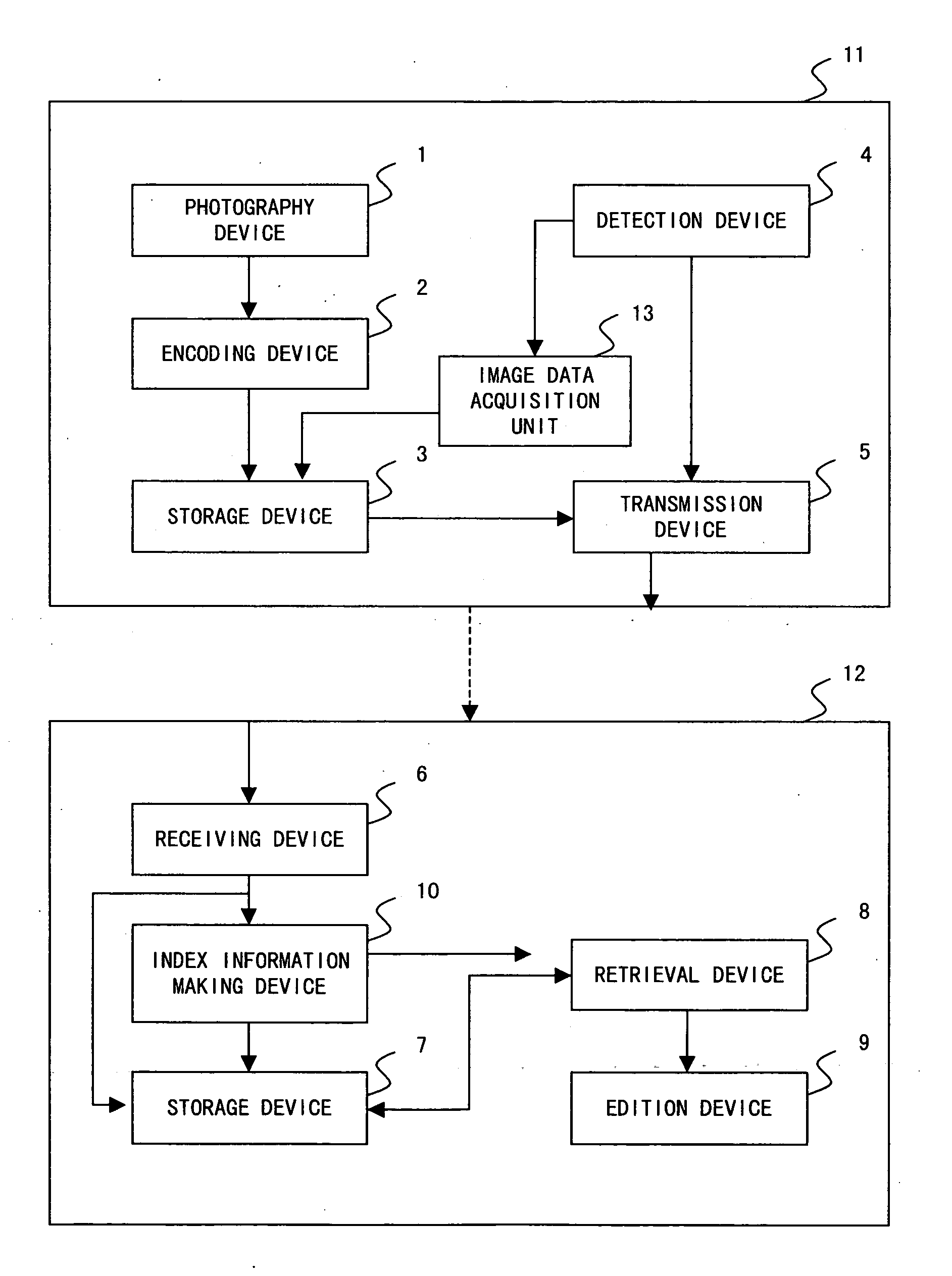
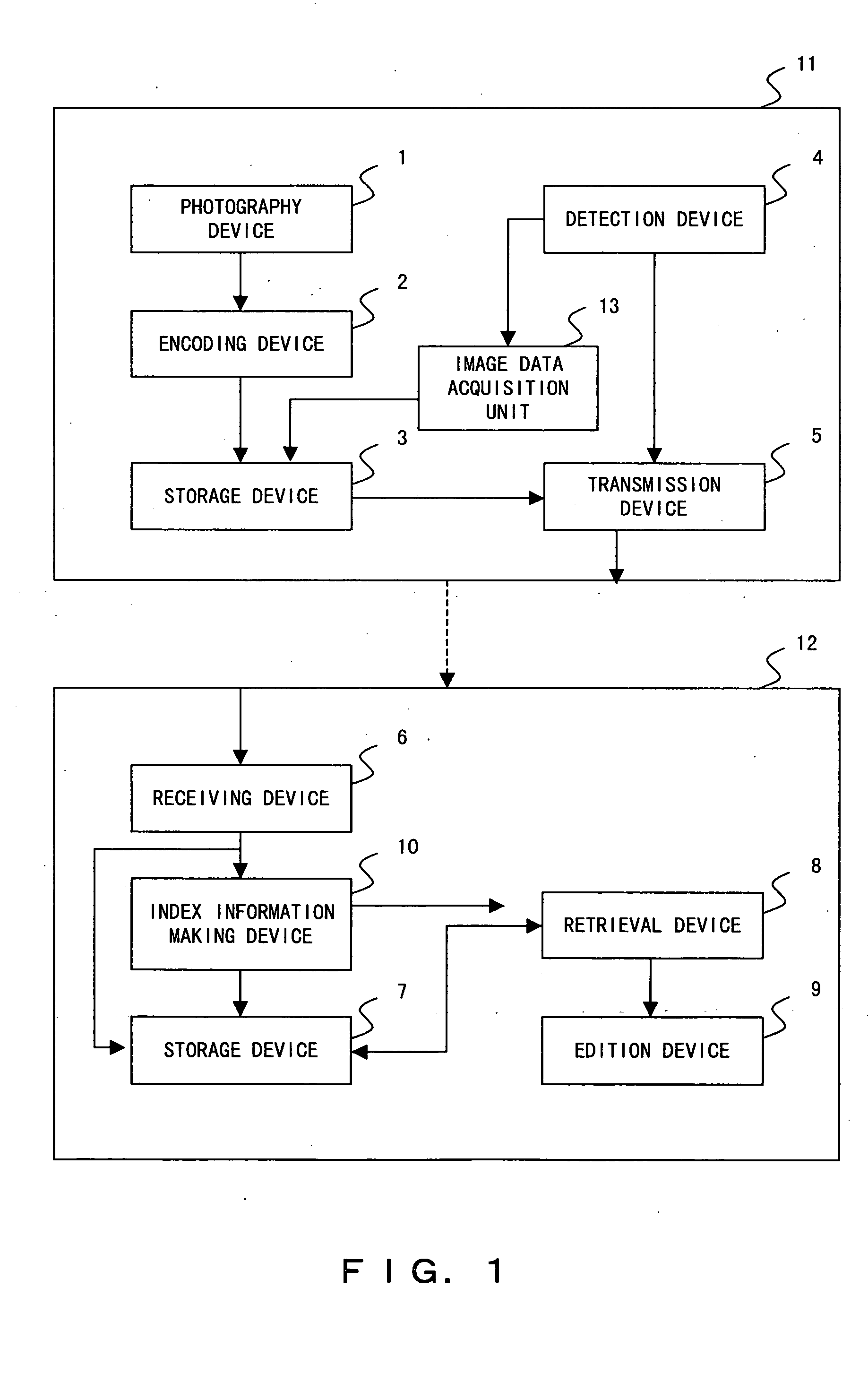
[0012] The purpose of the present invention is to efficiently retrieve image data of a specific moving object from the data of images photographed in a plurality of photographing positions.
[0016] According to this invention, it is possible to retrieve the image data of a moving object associated with a specific RFID from a vast amount data of images photographed in a plurality of photographing positions.
[0020] Thus, by constituting the method in such a way, it is possible to acquire the image data of a specific moving object from among a number of image data files and rearrange the image data chronologically in the order of the time when the moving object passes the photographing positions.
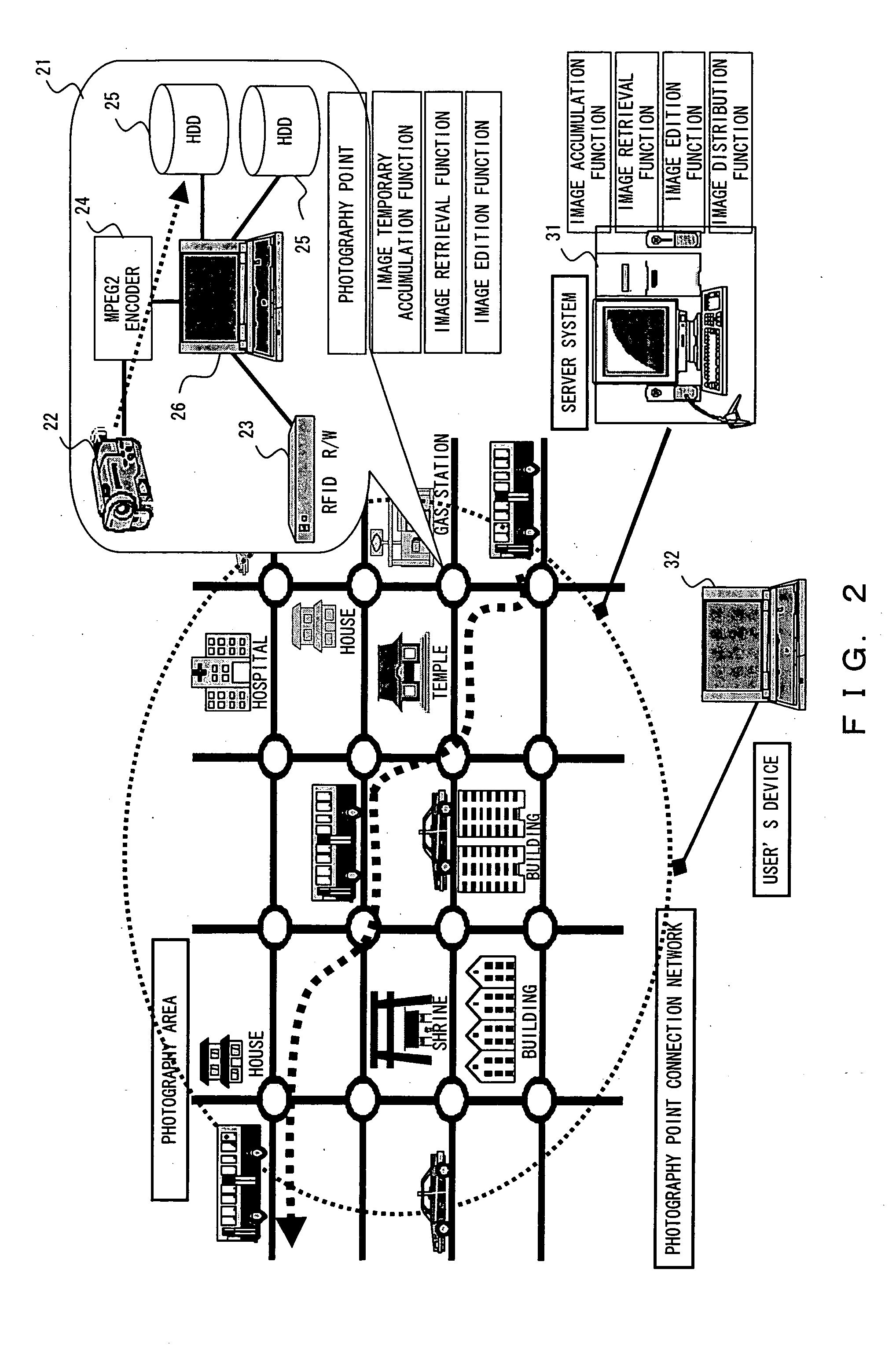
[0022] According to this invention, the image data of a moving object having a specific RFID can be easily retrieved from a vast amount of image data on the side of the accumulation system for accumulating the image data by transmitting the image data of the moving object in association with the detected RFID. Thus, it is possible to extract, for example, the image data of a specific moving object photographed in a plurality of photographing positions, collect said image data as an image data file, and confirm which path the moving object passes through.
[0030] By constituting the apparatus in such a way, the position in which the image data of the specific RFID is stored can be known by the index information, so the retrieval of image data can be speeded up because it is possible to find out the image data to be targeted without retrieving the image data file itself.

Problems solved by technology

In the conventional image accumulation system for moving objects, there was a problem in that since it was necessary to visually confirm a large number of images accumulated and retrieve the image of a specific object, it took a long time to retrieve the image.

Method used


Image

  • Method of retrieving image data of a moving object, apparatus for photographing and detecting a moving object, and apparatus for retrieving image data of a moving object
  • Method of retrieving image data of a moving object, apparatus for photographing and detecting a moving object, and apparatus for retrieving image data of a moving object
  • Method of retrieving image data of a moving object, apparatus for photographing and detecting a moving object, and apparatus for retrieving image data of a moving object

Examples


first embodiment

[0111] Next, described below is the processing of the server system 31 in a first embodiment with reference to the flowchart shown in FIG. 11. The same Step number is given to the same processing as in FIG. 3.

[0112] Each photography and detection apparatus 21a, 21b . . . 21n makes the moving object detection information file 41 which records the detection time for every RFID tag number and stores said file 41 in the storage device 25 (S19 in FIG. 11).

[0113] Also, each photography and detection apparatus 21a, 21b . . . 21n cuts out the image data of a moving object designated by an RFID tag number, makes the image data file 42 and stores it in the storage device 25 (S26), and then transfers the data to the server system 31 (S29).

[0114] The server system 31 collects the data transmitted from each photography and detection apparatus 21a, 21b . . . 21n installed in each photographing position (S51).

[0115] Then, the server system 31 makes a comparison table for comparing the moving ob...

second embodiment

[0139] the real-time index file 43 is made by each photography and detection apparatus 21a, 21b . . . 21n, and the server system 31 makes the real-time index file 43 which integrates the real-time index files 43 of each photography and detection apparatus 21a, 21b . . . 21n for every RFID tag number. It is possible to acquire the image data of a moving object having the same RFID tag number photographed in a plurality of photographing positions based on the integrated real-time index file 43, and acquire the chronological image data of the moving object which is designated by rearranging the acquired image data chronologically.

third embodiment

[0140]FIG. 16 is a flowchart showing the processing of the photography and detection apparatus in the present invention.

[0141] This third embodiment is characterized in that when a RFID tag is detected, the RFID reader-writer 23 writes accumulated contents information in the RFID tag of a moving object.

[0142] In the following description, the same Step number is given to the same processing as in FIG. 3, FIG. 5 and FIG. 7.

[0143] When the image data of the moving object of the designated RFID tag number is cut out based on the system operation initial setting value and said image data is stored in the storage device 25 (S26), the photography and detection apparatus 21 writes the accumulated contents information, for example, information concerning the photographing positions (detection points), the pattern of the acquired image data (pattern designated by an image data accumulation pattern), the name of the accumulated image data and so forth in the RFID tag of the moving object (S...


PUM


Abstract

The purpose of the present invention is to efficiently retrieve the image data of a specific moving object from the data of images photographed in a plurality of photographing positions. A number of photography and detection apparatuses having an RFID detection function and a photography function are arrayed in the positions where roads cross each other, and detect the RFID of a moving object which passes the photographing positions and transmit the image data of the moving object in association with the detected RFID to the server system. The server system stores the data of images photographed in a plurality of photographing positions in the storage device and retrieves the image data associated with the designated RFID from the storage device.

Description

BACKGROUND OF THE INVENTION [0001] 1. Field of the Invention [0002] The present invention relates to a method of retrieving image data of a moving object using RFID, an apparatus for photographing and detecting a moving object, an apparatus for retrieving image data of a moving object, a program for retrieving image data of a moving object, and a recording medium for recording an image data program. [0003] 2. Description of the Related Art [0004] In recent years, with the advance of a multi-media image technology which is represented by a digital compression technology of motion pictures, image information services have been provided in various fields, and further speedup and high quality are required. [0005] Particularly, a great deal is expected of the service of providing image information having a wide range of applications such as an application of detecting and recording the moving state of an object which is moving in a general life environment such as man, goods, vehicle or ...

Claims


Application Information

Patent Timeline
IPC IPC(8): G06K17/00G06F17/30G06K19/06G07C9/00G08G1/017H04N23/40
CPCG06K2017/0045G08G1/0175G07C2011/02G07C9/00111G07C9/28
Inventor HASEGAWA, MAKOTOYAMANAKA, TOSHIHIRO
Owner FUJITSU LTD
Learn More