
Tool holder and method of machining work using this tool holder

a tool holder and tool holder technology, which is applied in the direction of tool holders, turning machine accessories, manufacturing tools, etc., can solve the problems of drawing inherent in the nc lathe shown in figs, and the above-described tool holder, and achieve the effect of enhancing the versatility of the holder

Inactive Publication Date: 2005-10-06
CITIZEN WATCH CO LTD
View PDF4 Cites 7 Cited by
  • Summary
  • Abstract
  • Description
  • Claims
  • Application Information

AI Technical Summary

Benefits of technology

[0032] Moreover, a edge of the tool can be easily ground while the tool is attached to the holder, and accuracy of a edge position of the tool with respect to the holder or the holder body can be secured.
[0035] According to such a constitution, only by relaxing the attaching of the holder to the holder body, the engaging position between the holder and the holder body can be easily changed.
[0037] According to such a constitution, only by relaxing the attaching of the holder to the holder body, and pressing the engaging member again by changing a direction of the holder, different tools can be attached to the common holder to machine the work. In addition, by providing the engaging portions on the plurality of surfaces of the holder, the tool holder can be attached to the tool rest such that the attaching direction of the tool to the tool rest can be set parallel or perpendicular to each of the spindles rotated by gripping the work. Hence, versatility of the holder can be enhanced.

Problems solved by technology

However, a drawback is inherent in the NC lathe shown in FIGS.
However, problems have been inherent in the above-described tool holder.

Method used


Image

  • Tool holder and method of machining work using this tool holder
  • Tool holder and method of machining work using this tool holder
  • Tool holder and method of machining work using this tool holder

Examples


second embodiment

[0138] In a second embodiment described hereinafter, in addition to superpositions of the X1 and X2 axis, and the Z1 and Z2 axis, superposition of Z0 and Z1 axis is carried out.

[0139]FIG. 11 is a plan view illustrating a schematic configuration of an NC lathe according to the second embodiment of the present invention; and FIG. 12 a control block diagram of a controller in the NC lathe.

[0140] In FIGS. 11 and 12, portions and members similar to those of the first embodiment are denoted by reference numerals similar to those of FIGS. 5, 7 and 8, and detailed description thereof is omitted.

[0141] A spindle stock 120′ of an NC lathe 100′ of the second embodiment can be freely moved in the direction of the axis Z0 parallel to a Z axis. A movement of the first spindle stock 120′ in the direction of the axis Z0 is carried out by driving of a not-shown motor as a driver.

[0142] A second tool rest 180 is provided oppositely to a too rest 160. This second tool rest 180 can be freely moved ...


PUM

PropertyMeasurementUnit
distanceaaaaaaaaaa
diameteraaaaaaaaaa
Sizesaaaaaaaaaa

Abstract

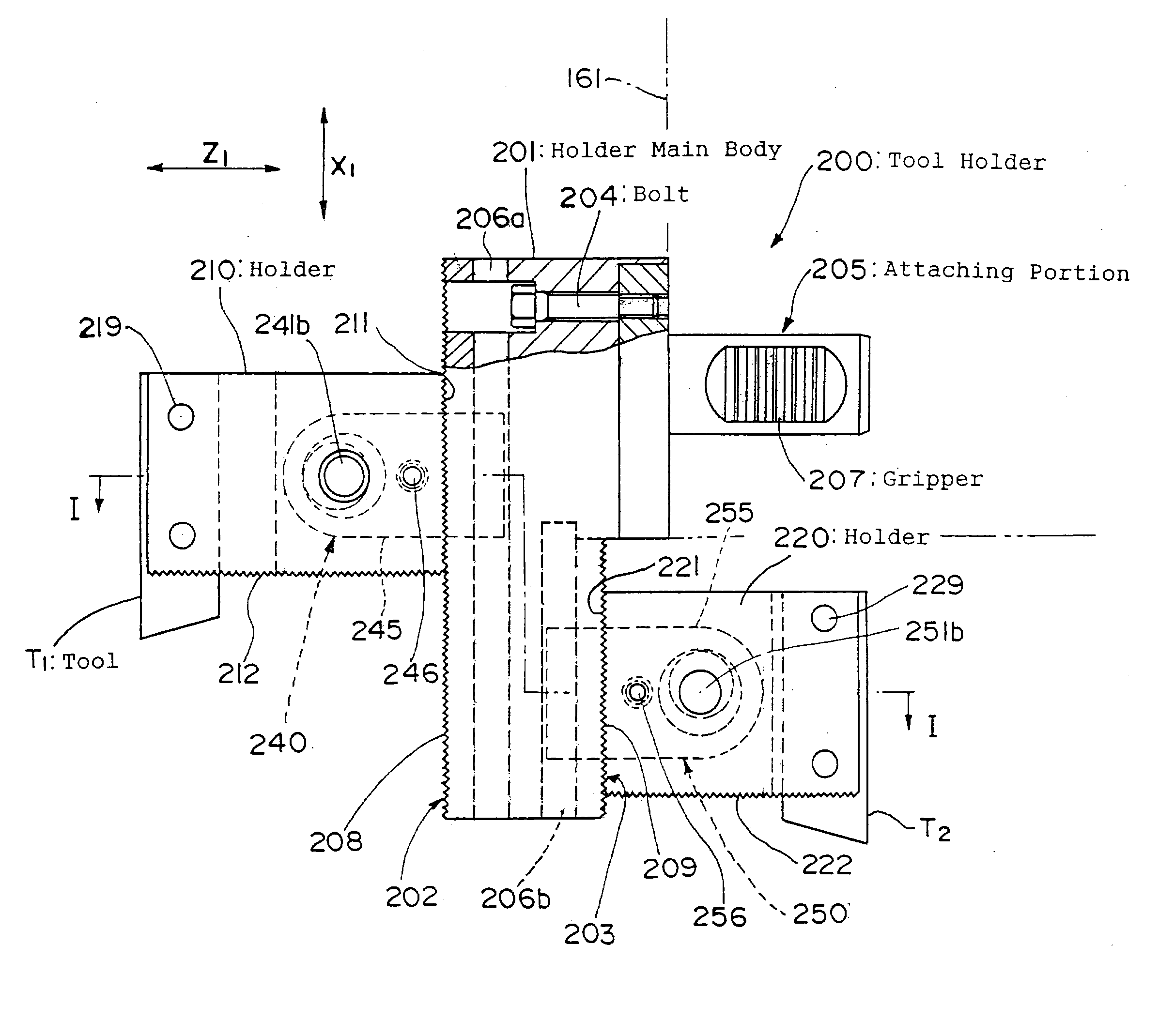
There is provided a tool holder capable of attaching a plurality of tools to one tool holder, and easily adjusting these tools in a positional relation suitable for work machining. The tool holder comprises a holder body 201 attached to a tool rest 160, a plurality of surfaces 202 and 203 formed around the holder body 201, holders 210 and 220 attached to the surfaces 202 and 203 and having tools for machining the work attached thereto, toothed portions 208 and 209 of tooth-shaped rows formed in a predetermined direction on the surfaces 202 and 203, engaging portions 211 and 221 formed on the surfaces of the holders attached to the surfaces 202 and 203, and engaged with the toothed portions to position the holders in predetermined positions of the surfaces 202 and 203, and attaching means 240 and 250 for attaching the holders to the holder body in engaging states between the toothed portions and the engaging portions.

Description

TECHNICAL FIELD [0001] The present invention relates to a tool holder for attaching tools to a tool rest of a machine tool, and a method of machining a work by the use of this tool holder. BACKGROUND ART [0002] To machine a work by a machine tool, a plurality of tools are attached to a turret type or comb-tooth type tool rest, and assigning a tool suitable for machining the work to a machining position. Then, the machining is carried out by rotating a spindle or the tool gripping the work or the like, and pressing the tool to the work. [0003] Especially, in a numerical control (NC) machine tool for automatically carrying out a series of machining steps, the tool is attached through a tool holder to the tool rest. If necessary, the tool can be easily exchanged together with the tool holder. [0004] One of such tool holders is disclosed in, for example, Japanese Patent No. 2878690, which can attach a plurality of tools to a holder body. [0005] FIGS. 16(a) to 16(c) are explanatory views...

Claims


Application Information

Patent Timeline
Patent Type & Authority Applications(United States)
IPC IPC(8): B23B3/30B23B9/10B23B29/20B23B29/24B23Q37/00B23Q39/02B23Q39/04
CPCB23B3/30B23B29/20B23B29/205B23B29/248B23B2260/132Y10T82/10B23Q39/02B23Q39/048Y10T82/2587Y10T82/2508B23Q37/00
Inventor SHINOHARA, HIROSHIMIYAZAKI, YUJIERNST, REINER
Owner CITIZEN WATCH CO LTD
Learn More