
Upstream data bypass device for a video system

Inactive Publication Date: 2005-09-29
BOSCH SECURITY SYST INC +1
View PDF16 Cites 4 Cited by
  • Summary
  • Abstract
  • Description
  • Claims
  • Application Information

AI Technical Summary

Benefits of technology

[0015] An advantage of the present invention is that display monitors connected to the video system are less affected by noise created by the data extraction and insertion of the bypass device.
[0016] Another advantage is that, when multiple video recei

Problems solved by technology

As mentioned above, the upstream data signal may include noise that is a result of imperfections in the data extraction process, poor termination quality, e.g., non-matching termination impedance at the monitor or some other video sink, and/or noise introduced

Method used


Image

  • Upstream data bypass device for a video system
  • Upstream data bypass device for a video system
  • Upstream data bypass device for a video system

Examples


Example

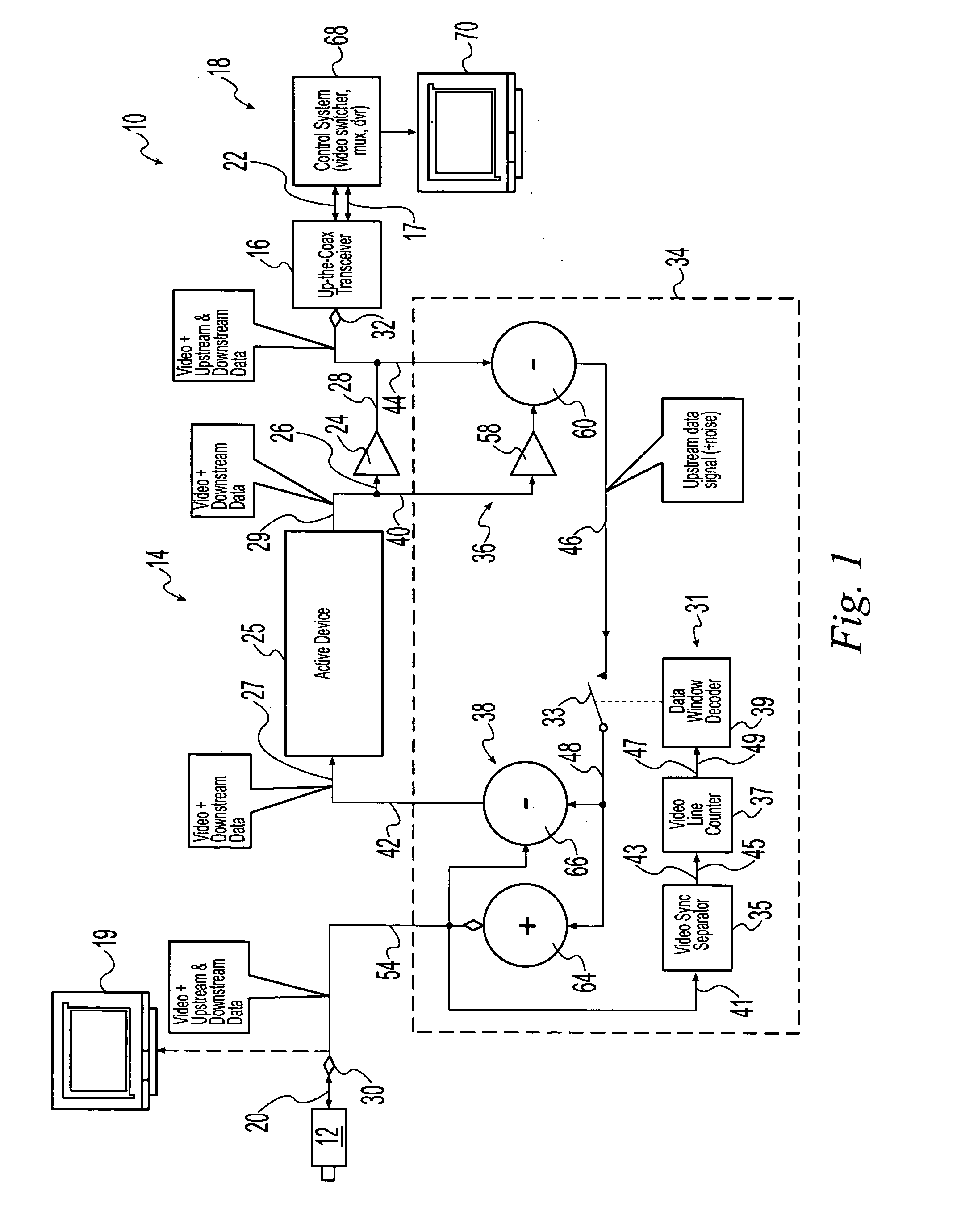
[0026] Corresponding reference characters indicate corresponding parts throughout the several views. Although the exemplification set out herein illustrates embodiments of the invention, in several forms, the embodiments disclosed below are not intended to be exhaustive or to be construed as limiting the scope of the invention to the precise forms disclosed.

DESCRIPTION OF THE PRESENT INVENTION

[0027] Referring now to the drawings and particularly to FIG. 1, there is shown one embodiment of a video system 10 of the present invention, including a video source 12, a video transmission apparatus (VTA) 14, an upstream coaxial type transceiver 16, an output-side video receiver 18, and an optional input-side monitor 19. Video source 12 may be in the form of a video camera with a transceiver for transmitting and receiving signals. That is, video source 12 may transmit a video output signal including active video signals and downstream data signals as well as receive upstream data signals v...


PUM


Abstract

A video system includes a video source transmitting an output signal on a transmission line. The output signal has a format such that first portions of the output signal include active video signals and second portions of the output signal lack active video signals. Each of a plurality of video receivers displays images based upon the active video signals and transmits a respective data signal on a respective one of a plurality of ports. A distribution device is electrically connected to the transmission line and to each of the ports. The distribution device transmits each of the data signals to the video source on the transmission line only during time periods when the second portions of the output signal are being transmitted on the transmission line. The distribution device includes a plurality of amplifiers, each having an input and an output. Each of the amplifiers receives signals on the input for transmission on the output as amplified signals. Each amplifier blocks signals received on the output from being transmitted on the input. Each amplifier transmits a respective amplified signal to a respective one of the receivers on a respective one of the ports. Each of the amplified signals is dependent upon the output signal and upon a data signal transmitted on the transmission line from the receivers other than the respective receiver.

Description

BACKGROUND OF THE INVENTION [0001] 1. Field of the Invention [0002] The present invention relates to video data transmission systems, and, more particularly, to a bypass device for upstream video data transmission systems. [0003] 2. Description of the Related Art [0004] Video systems commonly include an input video source, such as a camera, that transmits active video signals and data signals in a downstream direction to at least one output receiver, such as a video monitor. The receiver may receive both the active video signals and the data signals on a single, respective port. The video systems also often include one or more active devices, such as amplifiers, between the video source and the receiver. The amplifiers may operate to amplify, i.e., increase, the magnitude of, the active video signals and data signals so that the signals can be more readily used by the receiver. [0005] It may be desirable to transmit data signals from the receiver to the video source in an upstream d...

Claims


Application Information

Patent Timeline
IPC IPC(8): H04N7/04H04N7/088H04N7/10H04N7/16H04N7/173
CPCH04N7/088H04N7/106H04N7/102
Inventor CORBIN, SCOTT A.
Owner BOSCH SECURITY SYST INC
Learn More