
Embedded picture PSNR/CRC data in compressed video bitstream

a video bitstream and embedded picture technology, applied in the field ofsignal codecs, can solve the problems of difficult operation, high cost of conventional real-time video testing devices, and insufficient judgment, and achieve the effect of reliable and robust error

Active Publication Date: 2005-09-29
AVAGO TECH INT SALES PTE LTD
View PDF12 Cites 77 Cited by
  • Summary
  • Abstract
  • Description
  • Claims
  • Application Information

AI Technical Summary

Benefits of technology

[0009] The objects, features and advantages of the present invention include providing a method and / or apparatus that may (i) insert peak signal-to-noise ratio values for encoded video pictures into an encoded bitstream, (ii) insert video reconstruction data cyclic redundancy check or checksum information into the encoded bitstream, (iii) report peak signal-to-noise ratio values extracted from the encoded bitstream at a decoding side, (iv) report the cyclic redundancy check or checksum information at the decoding side, (v) provide a reliable and robust error detection method for verified data and / or (vi) provide a simple error detection method optimized for software implementation.

Problems solved by technology

The visual judgement is commonly not accurate enough to adjust some parameters used in encoding and / or decoding, thus resulting in a sub-optimal encoder setup.
Due to errors (both run time and design) in the encoder system, the decoder system and / or in a transmission path, the decoder system might generate incorrectly reconstructed video data.
However, the conventional real-time video testing devices are very expensive and hard to operate.
The decoded video-only measuring devices are also very expensive and cannot report a degradation level caused by the encoding process since no reference exists to compare with the decoded video.
A process of tuning a quality using the software-based codecs and the reconstructed video data can be very time and resource consuming since the reconstructed (i.e., uncompressed) video data uses a significant amount of storage space.
The lack of information causes difficulties in correlating the video and the reported quality with a picture level accuracy for different picture types and / or during transition periods.
A verification of the reconstruction processes has difficulties similar to the video quality process.
An amount of storage space needed for long sequences of reconstructed video data is significant.
A verification with real-time encoders is often difficult since conventional real-time encoders do not output the internally reconstructed video data.

Method used


Image

  • Embedded picture PSNR/CRC data in compressed video bitstream
  • Embedded picture PSNR/CRC data in compressed video bitstream
  • Embedded picture PSNR/CRC data in compressed video bitstream

Examples


Embodiment Construction

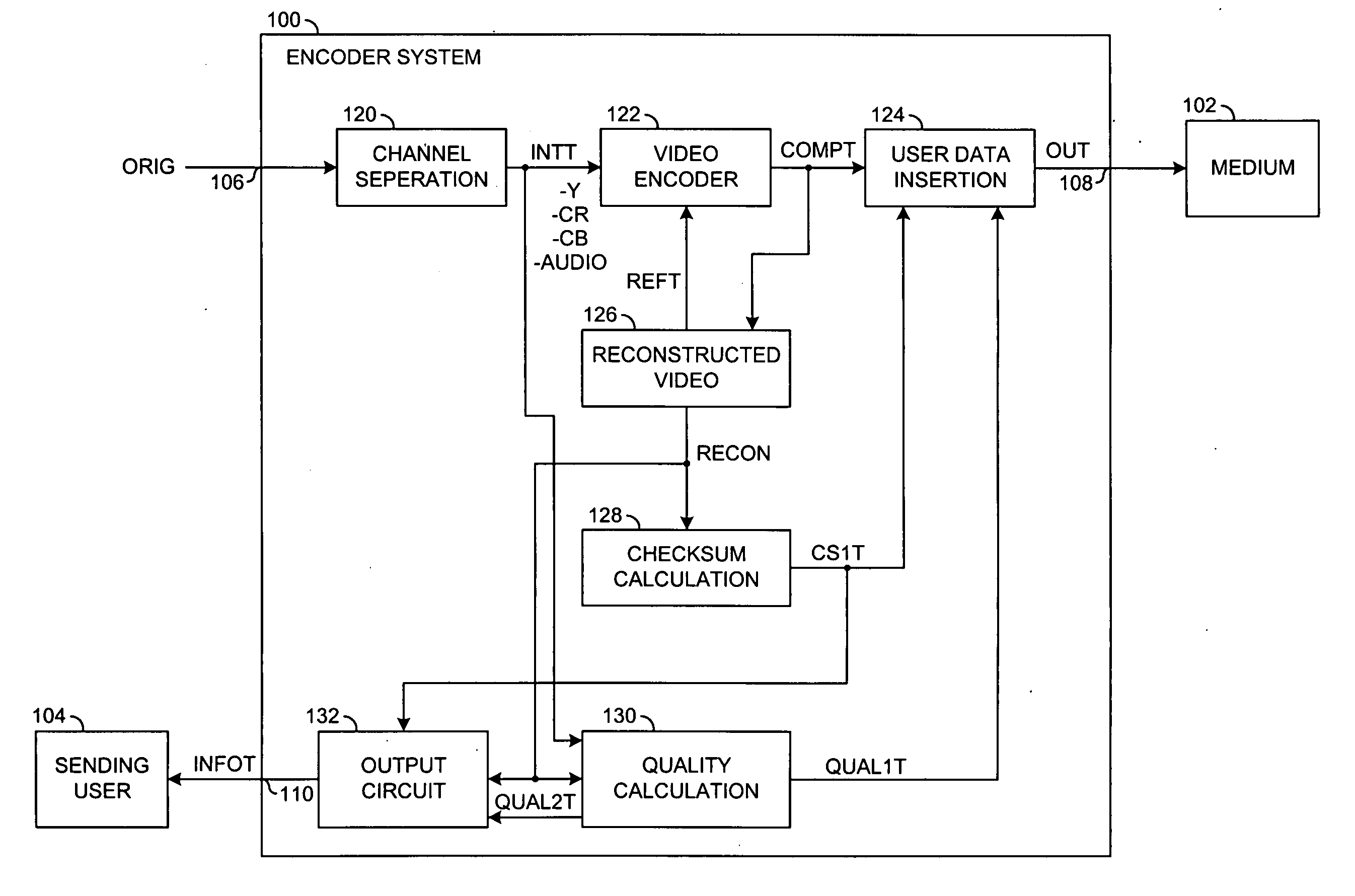
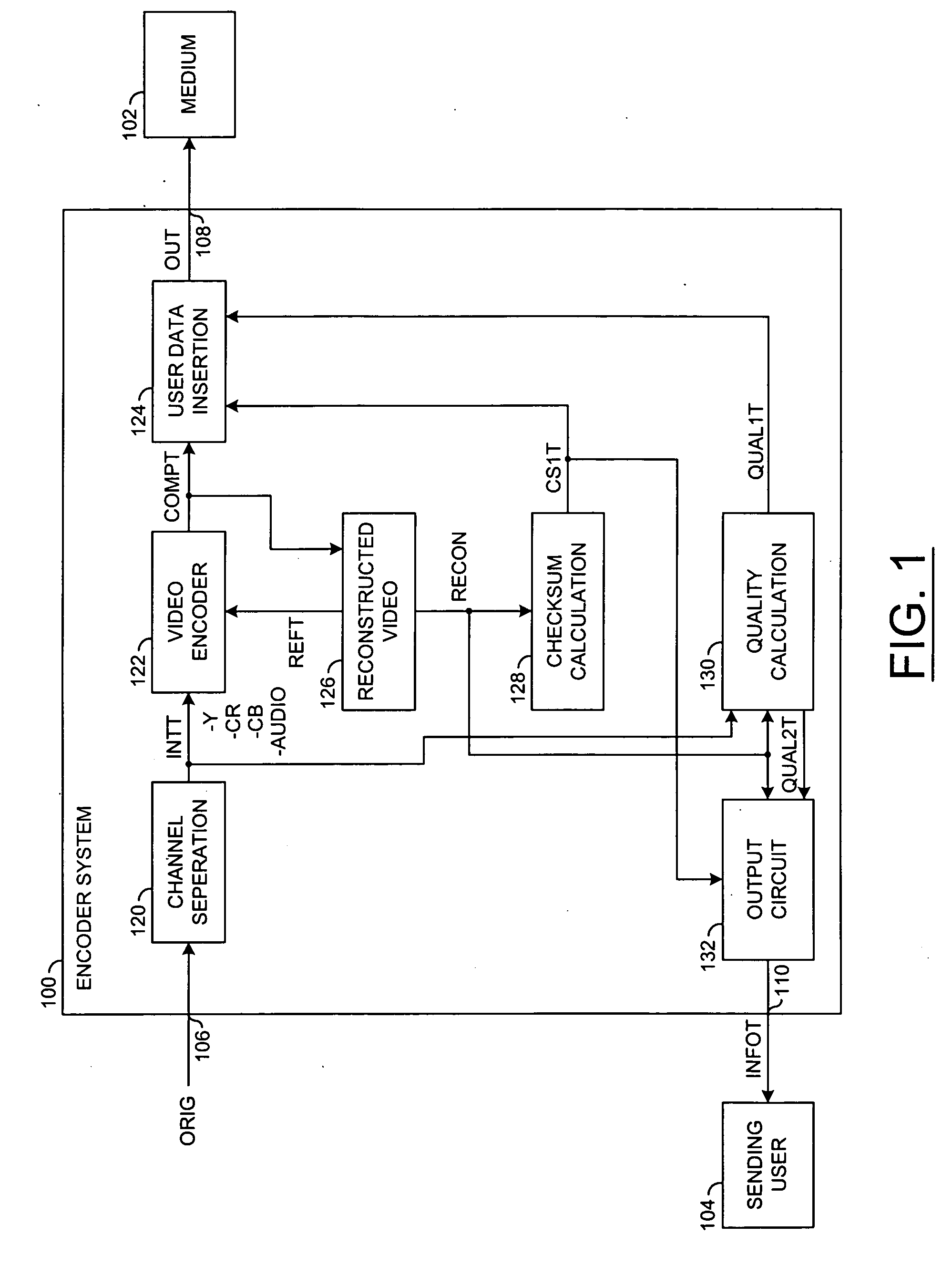
[0017] Referring to FIG. 1, a block diagram of an example implementation of a system 100 is shown in accordance with a preferred embodiment of the present invention. The system 100 may be implemented as an encoder system or circuit. The encoder system 100 may interface with a medium 102 and a sending user 104. A signal (e.g., ORIG) may be received at an input 106 of the encoder system 100. A signal (e.g., OUT) may be presented at an output 108 of the encoder system 100 to the medium 102. A signal (e.g., INFOT) may be presented at an output 110 of the encoder system 100 to the sending user 104. The medium 102 may be implemented as a transmission medium and / or a storage medium.

[0018] The signal ORIG may represent an original signal received by the encoder system 100 for compression. The signal ORIG may be implemented as one or more video, audio and / or data signals. As illustrated by the example in FIG. 1, the signal ORIG may be implemented as a composite signal simultaneously carryin...


PUM


Abstract

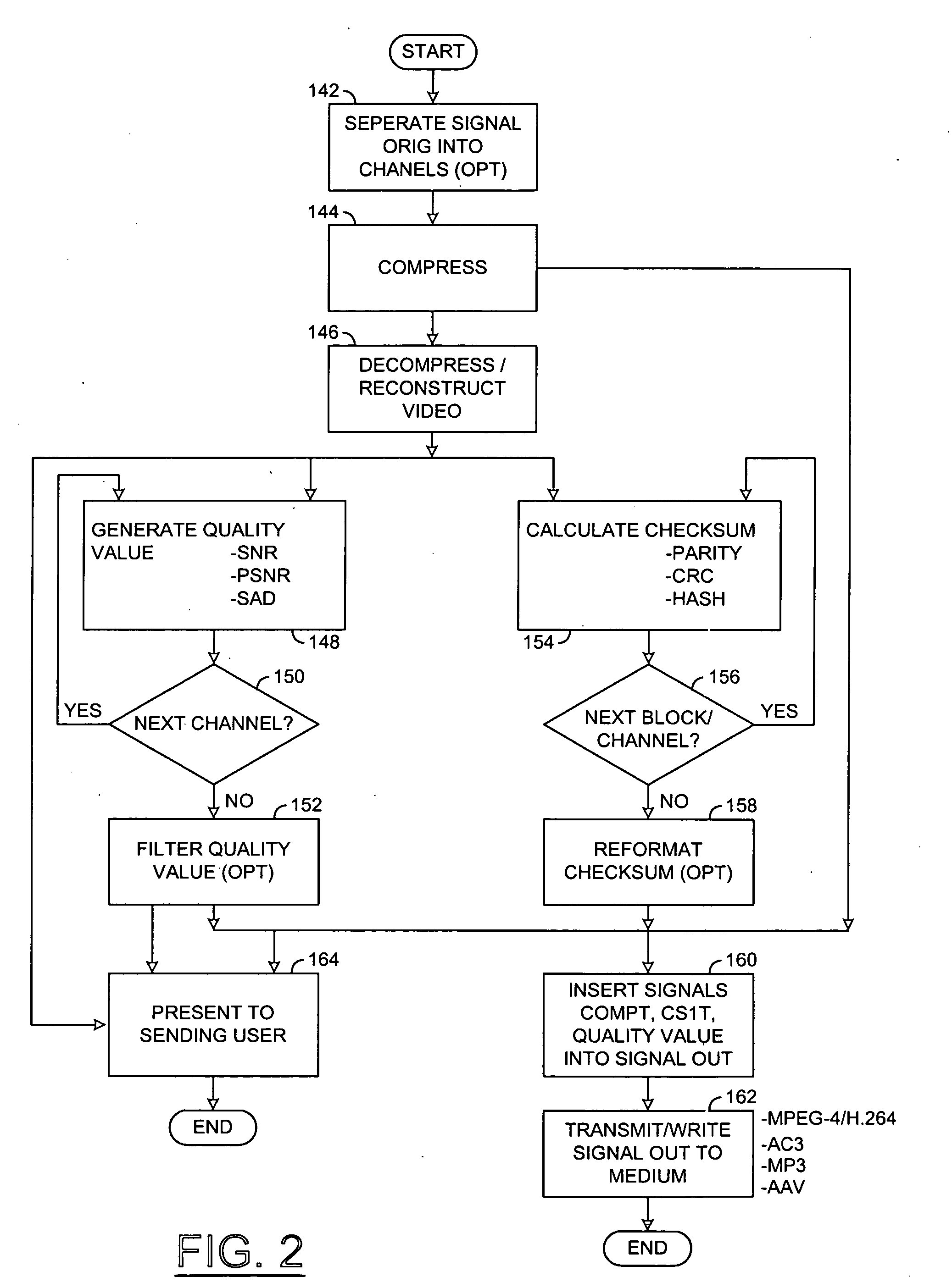
A method for processing an input signal is disclosed. The method generally includes the steps of (A) extracting a compressed signal and a first checksum from the input signal, (B) generating a decompressed signal by decompressing the compressed signal, (C) calculating a second checksum for the decompressed signal and (D) generating a result by comparing the first checksum to the second checksum.

Description

FIELD OF THE INVENTION [0001] The present invention relates to signal codecs generally and, more particularly, to embedding peak signal-to-noise and / or cyclic redundancy check data in a compressed video bitstream. BACKGROUND OF THE INVENTION [0002] Conventional real-time video encoder systems are configured to produce video with requested parameters and visual quality. An encoded video bitstream generated by the real-time video encoder systems does not contain any numerical information about the video quality. Therefore, picture quality is checked visually after decoding the encoded video bitstream with a decoder system. The visual judgement is commonly not accurate enough to adjust some parameters used in encoding and / or decoding, thus resulting in a sub-optimal encoder setup. [0003] A conventional standard-compliant decoder system should produce reconstructed video data that is the same to reconstructed video data generated by the encoder system in a feedback path. Due to errors (...

Claims


Application Information

Patent Timeline
IPC IPC(8): H03M13/00H04N7/26H04N7/66
CPCH04N19/46H04N19/70
Inventor NOVOTNY, PAVELCOTE, GUYWINGER, LOWELL L.
Owner AVAGO TECH INT SALES PTE LTD
Learn More