
Integrated precision machine design system and method

a technology of precision machine design and integrated system, applied in the field of precision machine design, can solve the problems of inability to meet the needs of the precision motion control industry, inability to manufacture goods without the use, and varies in automation complexity, so as to reduce machine development time and costly errors, and increase engineering productivity.

Inactive Publication Date: 2005-09-29
RADIGAN THOMAS J +1
View PDF34 Cites 15 Cited by
  • Summary
  • Abstract
  • Description
  • Claims
  • Application Information

AI Technical Summary

Benefits of technology

[0014] It is an object of the present invention to provide a system and method that brings the knowledge of precision machine design into an integrated and intelligent environment for practicing engineers and engineering students. It is another object of the present invention to provide a system and method to enable engineers and engineering students to perform various simulations and optimizations. It is still another object of the present invention to provide a system and method that will provide a competitive advantage in the global marketplace by increasing engineering productivity and reducing machine development time and costly errors.
[0021] The method employed by the present invention is useful both for training engineers and for facilitating the design, modeling and optimizing functions of precision machine development engineers. The method includes the ability of the engineer or engineering trainee to query the electronic training database. The method begins with the engineer or engineering trainee receiving specifications for a precision machine. The engineer either understands the specifications, in which case he then selects between either a system level or a component level specification, or, if the engineer does not understand what technologies are available for use in meeting the specifications, the engineer may query the electronic training database by topic or application. A list of descriptions of technical specifications is selected by the system in response to the query. The list may include general industry information to specific information relating to use of the present invention. This list will help the engineer or engineering trainee understand the available technologies to meet the specifications.

Problems solved by technology

Although knowledge-based systems have been devised, these have been very specific and fail to address the needs of the precision motion control industry.
In many cases, goods cannot be manufactured without the use of automated manufacturing lines.
The automation complexity, however, varies significantly as does the process requirements.
However, this is rarely the case.
Also, courses that teach relevant design methodologies are not uniform between schools and availability is usually at the graduate level, if at all.
Thus, the engineer that obtains a degree from a U.S. institution often does not have the required skill set for an employer in the precision capital equipment market.
On-the-job training can be provided by the employer but at a cost in lost efficiency and productivity.
This design process, while currently necessary, again comes at the cost of lost efficiency and productivity.
While industry information is plentiful, it can be time consuming to gather and take years to truly understand.
In addition to the above problems, the industries typically follow a cyclical business pattern and often lose highly trained workers during downturns through layoffs and attrition.

Method used


Image

  • Integrated precision machine design system and method
  • Integrated precision machine design system and method
  • Integrated precision machine design system and method

Examples


Embodiment Construction

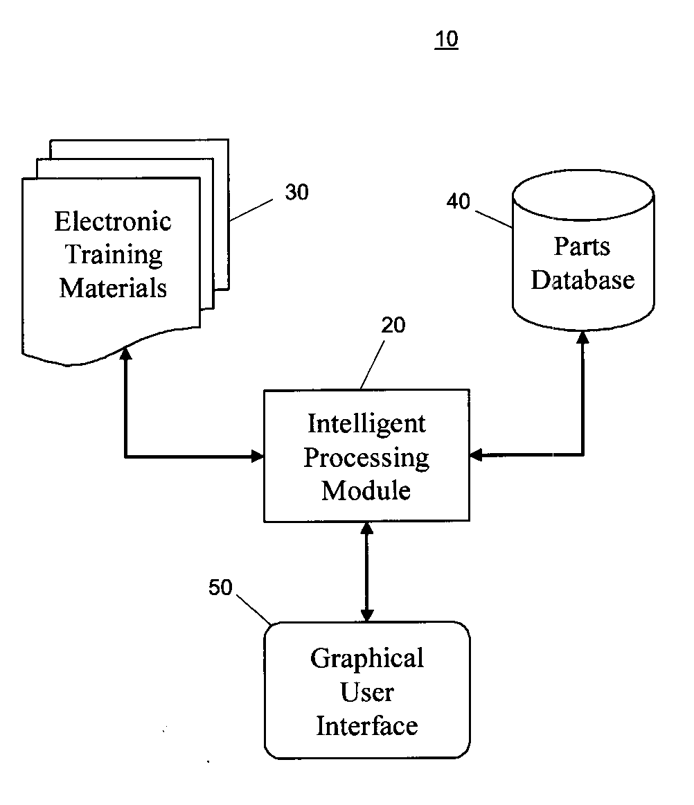
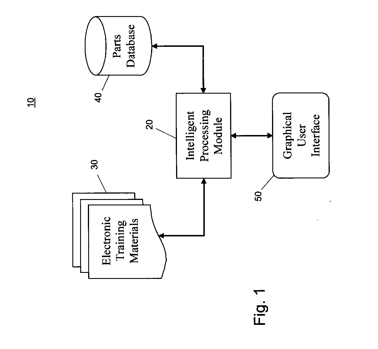
[0034] The preferred embodiment of the present invention is illustrated in FIGS. 1-6. FIG. 1 is a block diagram illustrating the major components of an integrated precision design system 10. Integrated precision design system 10 includes an intelligent processing module 20, an electronic training materials database module 30, a parts database module 40, and a graphical user interface module 50. Intelligent processing module 20 has two-way communication / data transfer with the electronic training materials database module 30, the parts database module 40 and the graphical user interface module 50. Using the above components, the present invention provides a method and apparatus for training engineers in precision machine development and for facilitating precision machine development engineers in designing precision machines to predefined specifications. Predefined specifications mean the machine requirements that must be met in order to meet the industry process requirements.

[0035] I...


PUM


Abstract

An integrated precision machine design system includes an intelligent processing module, a parts database module coupled to the processing module, a training materials database module coupled to the processing module, and program code configured for receiving a user-specified precision machine design specification where the program code is operably coupled to the processing module to compute design system properties using data from the parts database module based on the user-specified precision machine design specification.

Description

[0001] This application claims benefit of U.S. Provisional Application No. 60 / 557,215, filed Mar. 29, 2004.BACKGROUND OF THE INVENTION [0002] 1. Field of the Invention [0003] The present invention relates generally to precision machine design. Particularly, the present invention relates to an integrated system and method in precision machine design that facilitates both the training and design process. [0004] 2. Description of the Prior Art [0005] There have been various knowledge-based engineering systems devised to date to help the engineer design specific products. These knowledge-based engineering systems are used for specific applications such as gear design, HVAC air-handling assemblies for a climate control system, variable speed AC motors, machinery component selection, component placement system for circuit board components, structural members for a building frame, power supplies, etc. Although knowledge-based systems have been devised, these have been very specific and fai...

Claims


Application Information

Patent Timeline
IPC IPC(8): G06F17/50G06F19/00
CPCG06F17/50G06F30/00
Inventor RADIGAN, THOMAS J.CHIN, HARRISON H.
Owner RADIGAN THOMAS J
Learn More